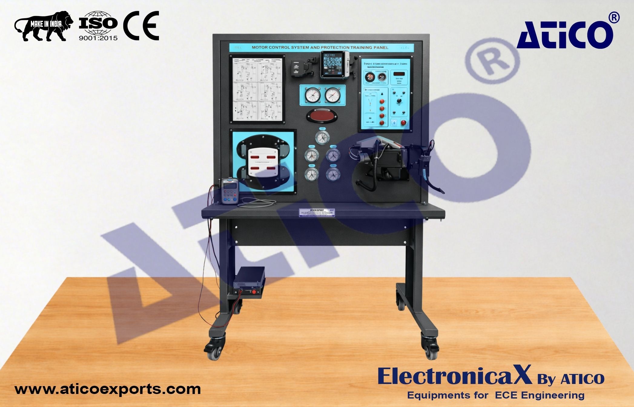
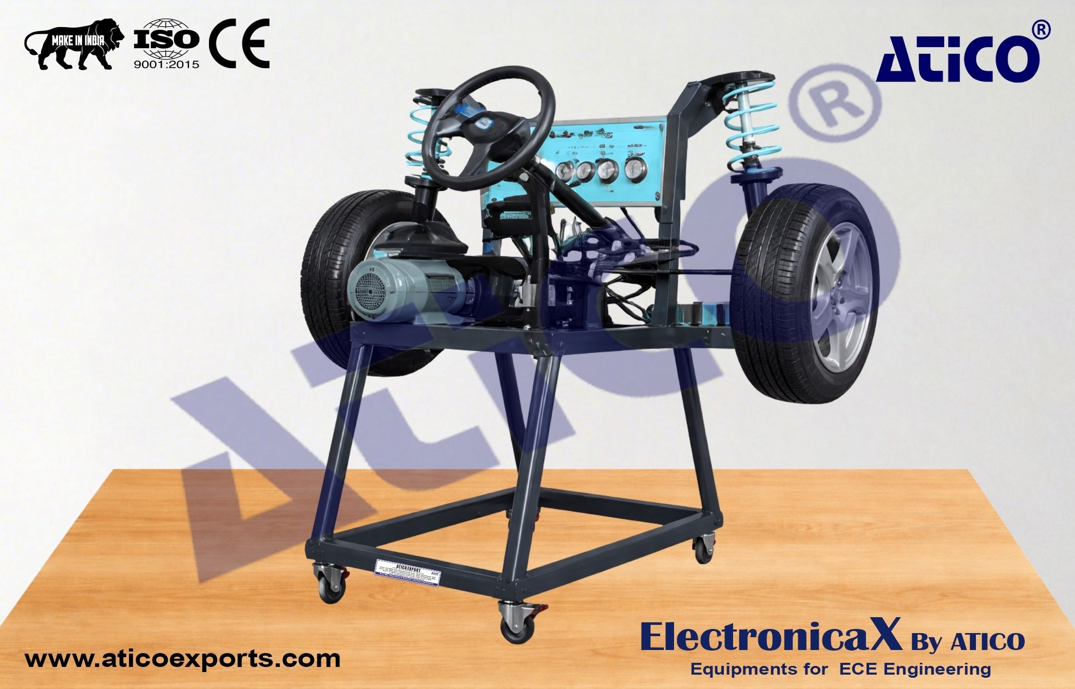
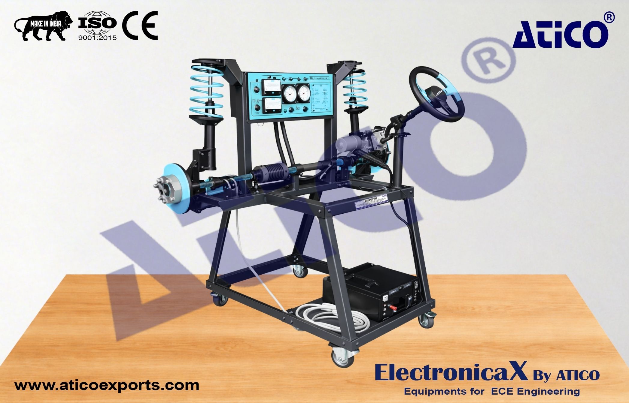
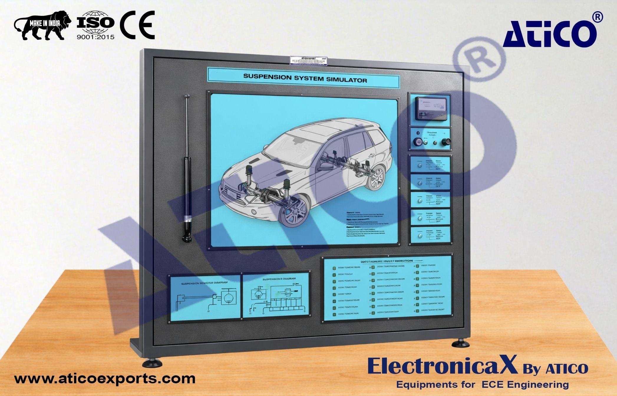
Four rotative wheels with wheel sensors, with digital speed display for each wheel (4 digital displays)
4 variable speed electrical drive systems for each wheel to control individual wheel speed
ABS hydraulic modulator (actuator) unit which is controlled by on-board computer system (ECU)
Five brake line pressure gauges to show pressure differentials from master brake cylinder to individual wheels
Brake Master Cylinder with Vacuum assist booster mechanism and brake pedal assembly
Demonstration of entire feature process schematic for graphic illustrations clearly explaining operation of entire ABS braking system
A control panel is provided with ON/OFF power supply system light (POWER ON, ABS warning light) indicating operational status
Volt and Ampere meters to measure DC input power and brake light to show operation of braking system just as on the vehicle
Special Track Conditions and Performance Display Panel: displays controls for road conditions (dry asphalt, wet asphalt, icy snow) and allows simulation of wheel speeds in seconds; individual controls for wheel speeds, one for each wheel