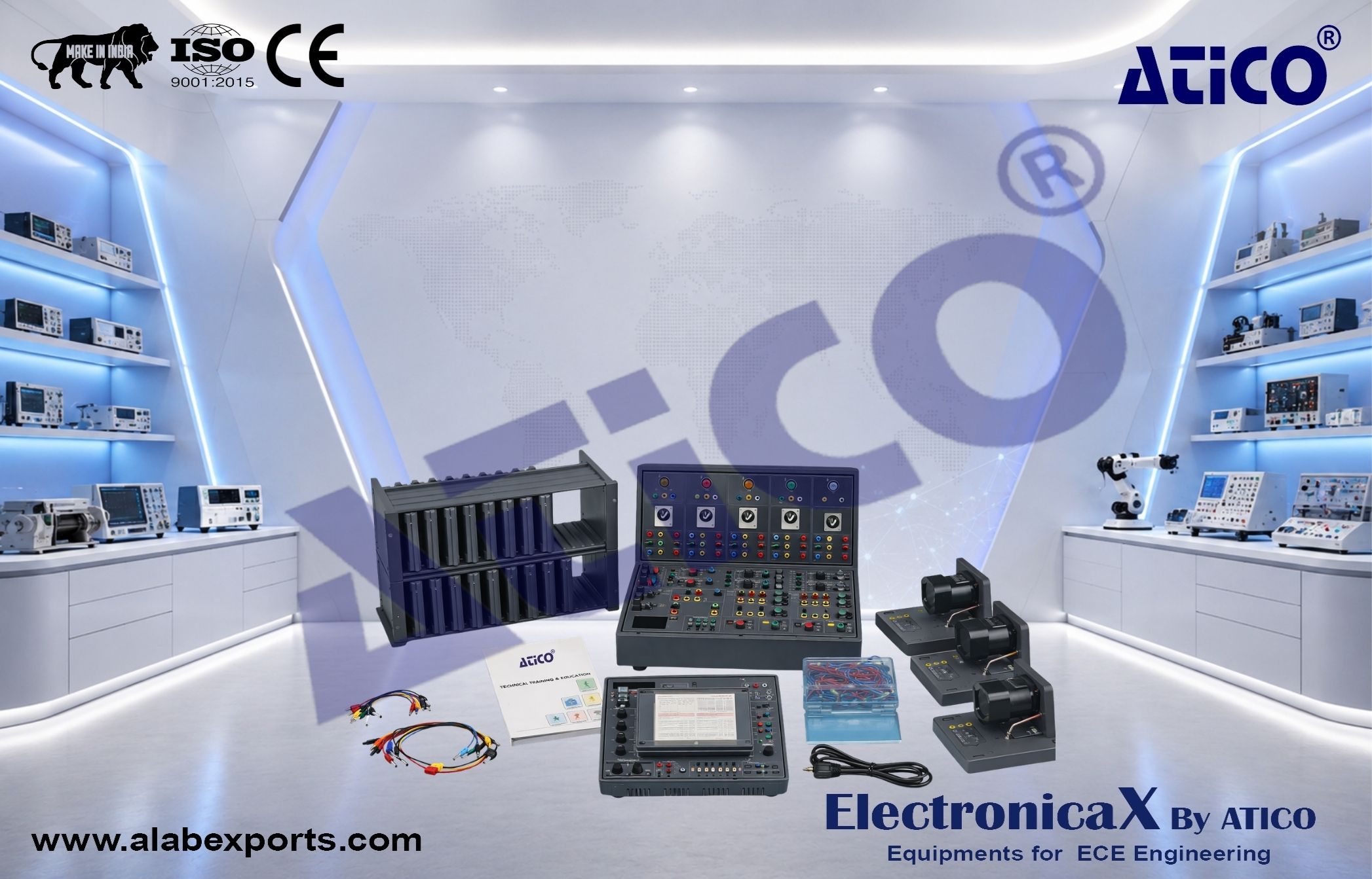
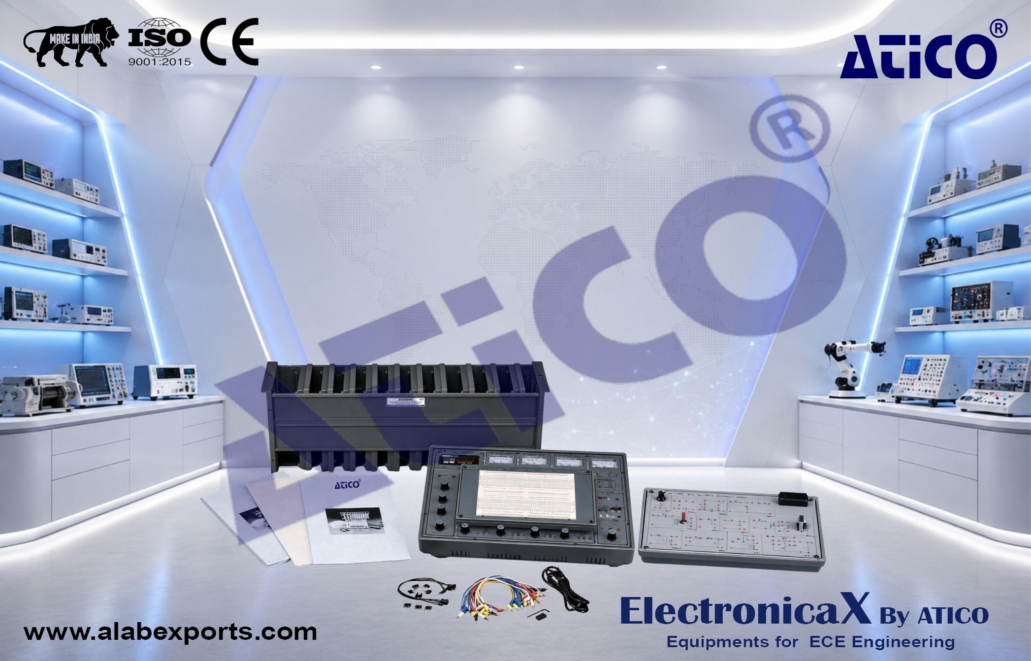
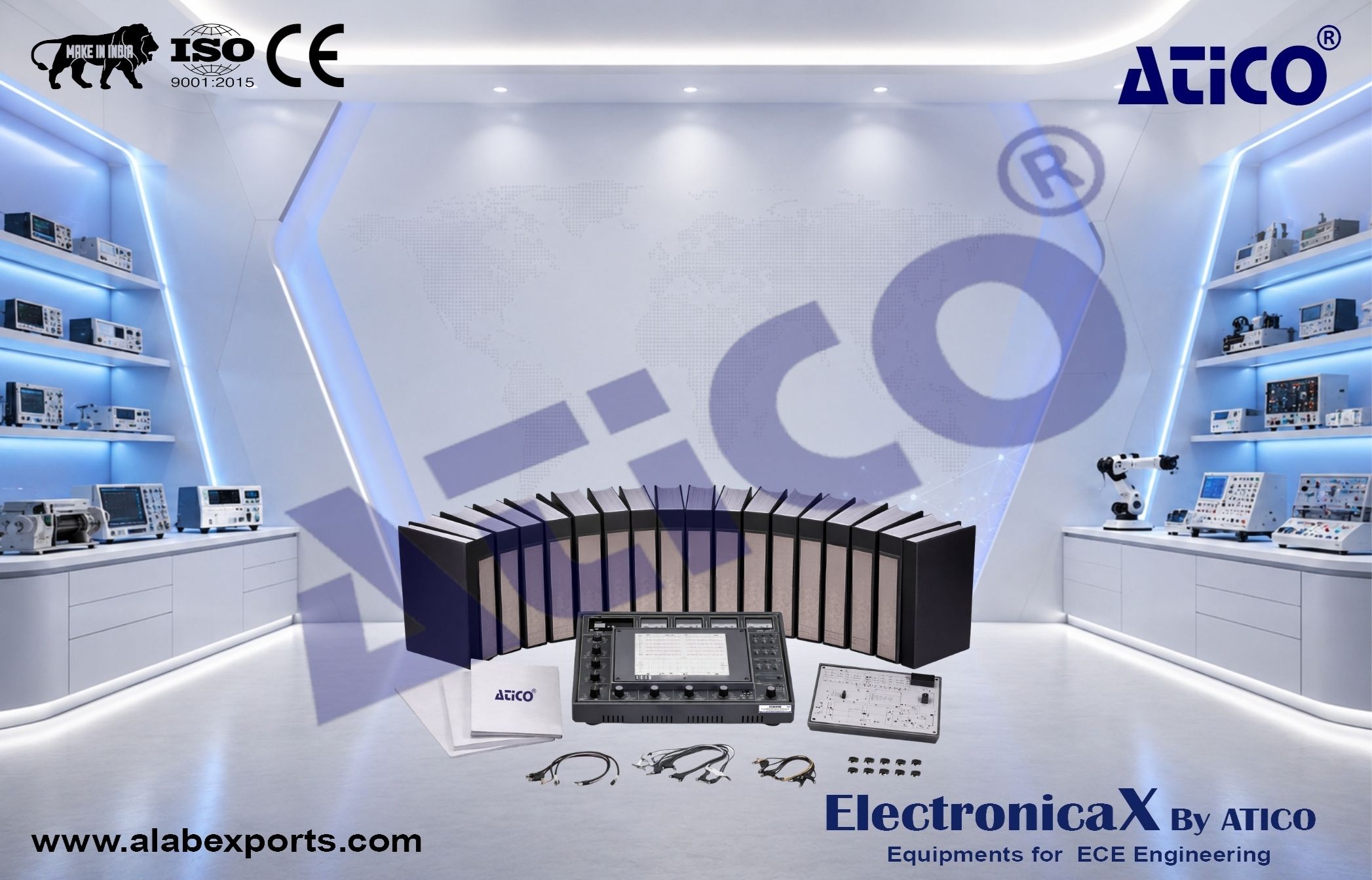
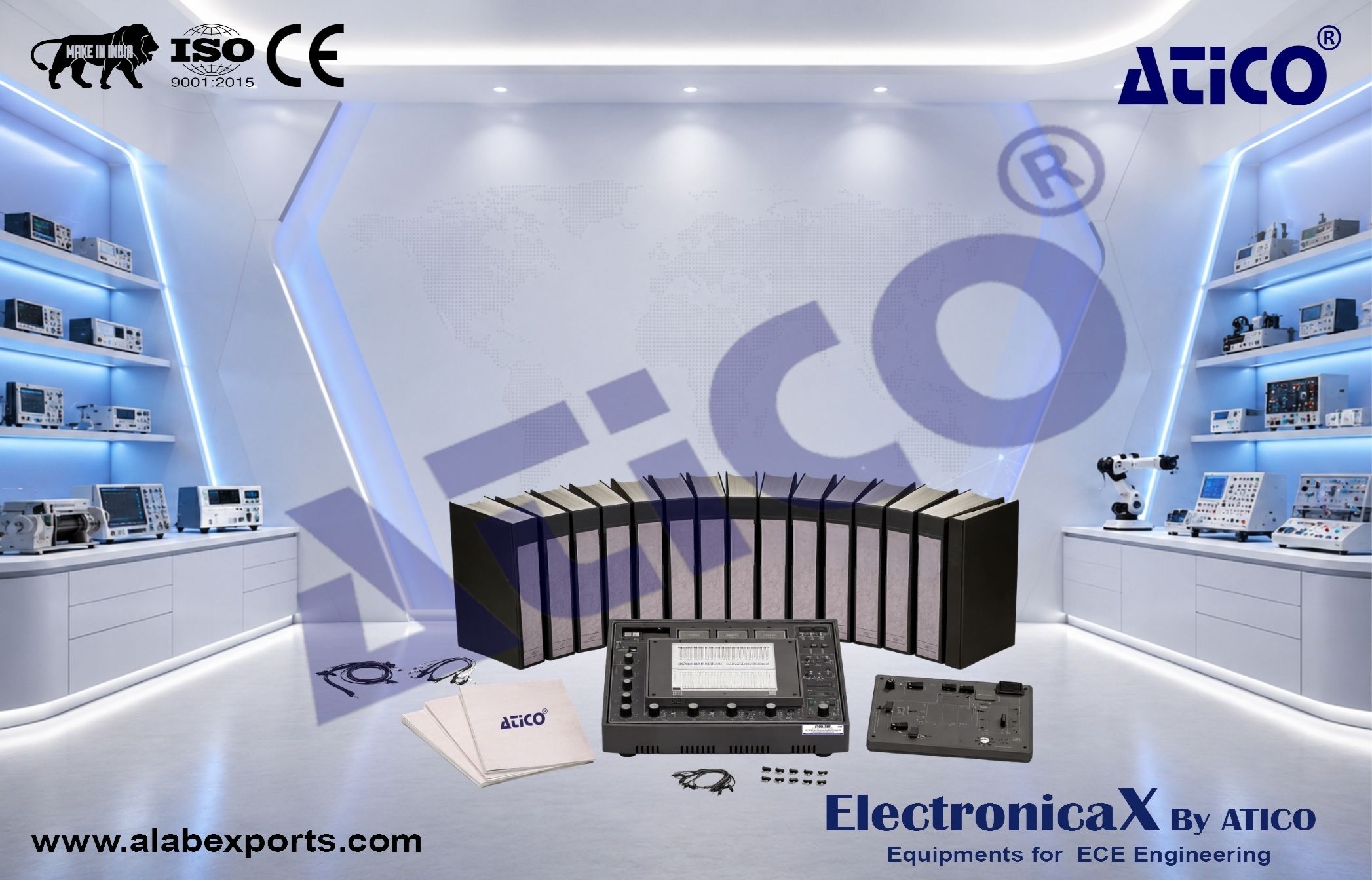
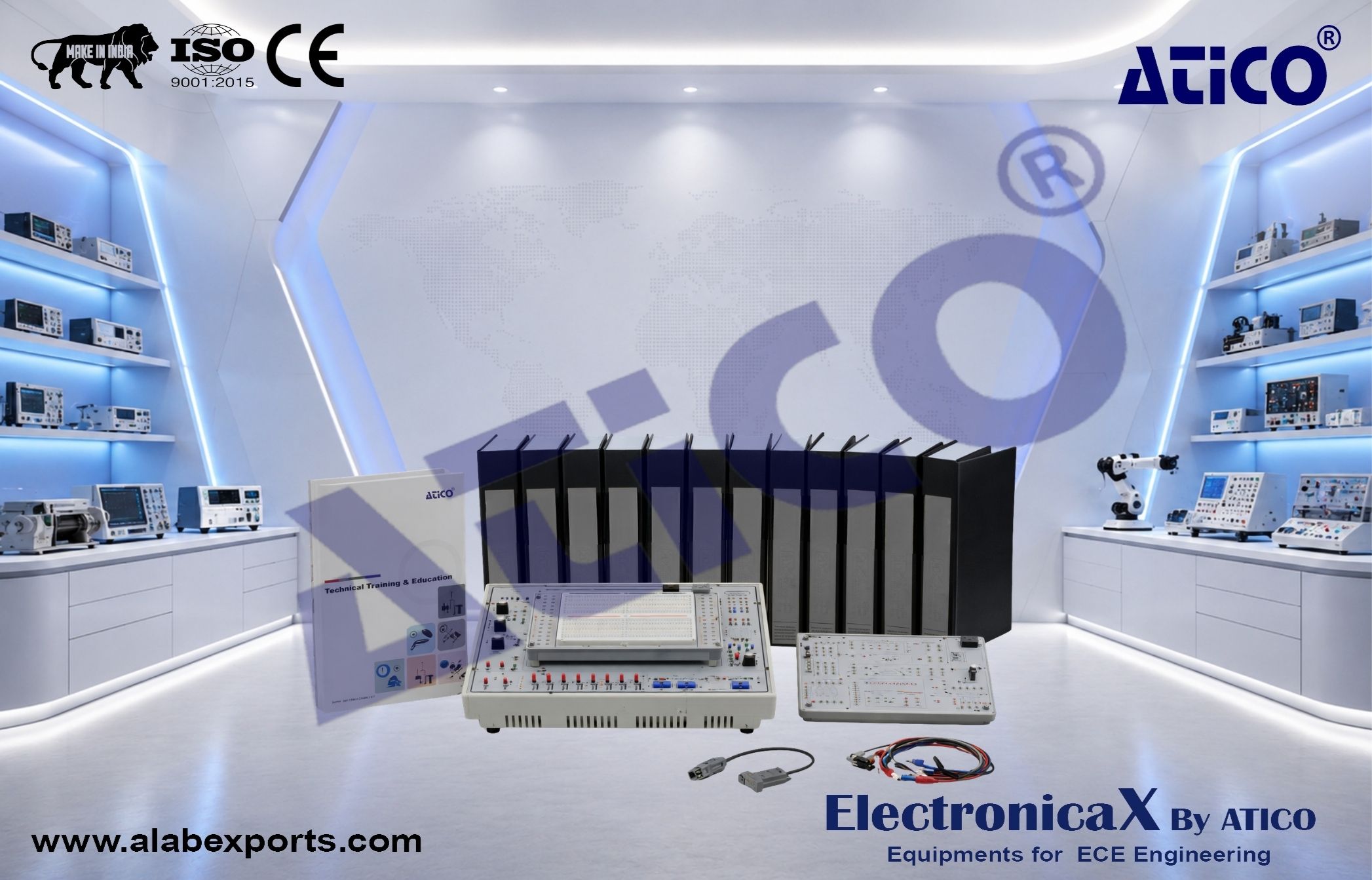
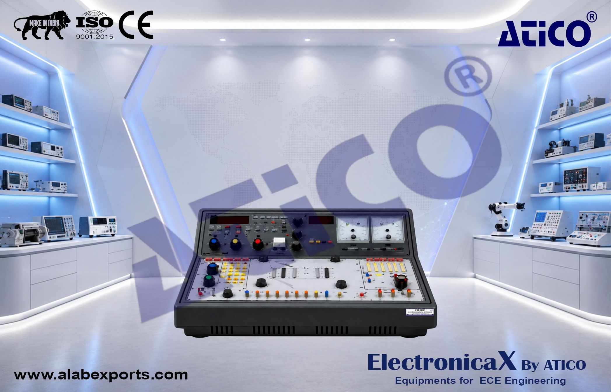
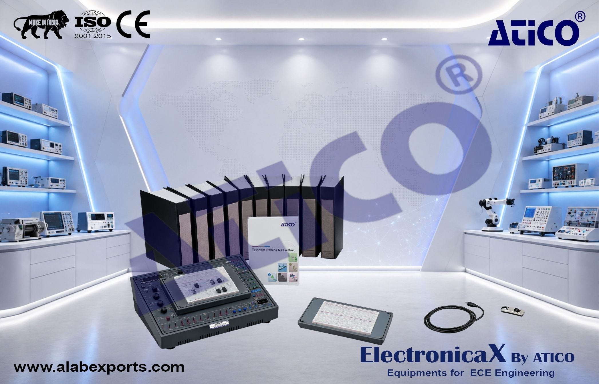
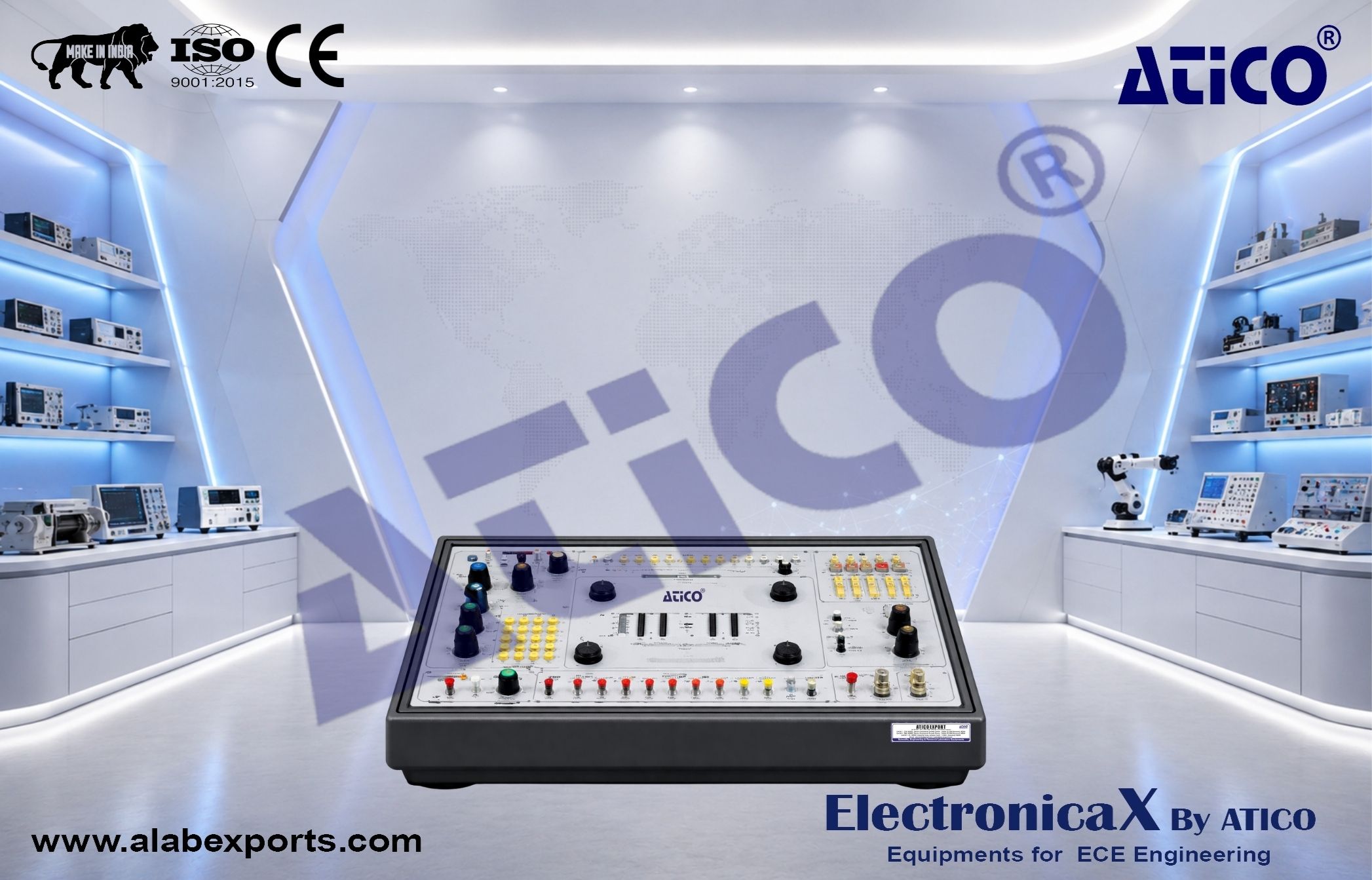
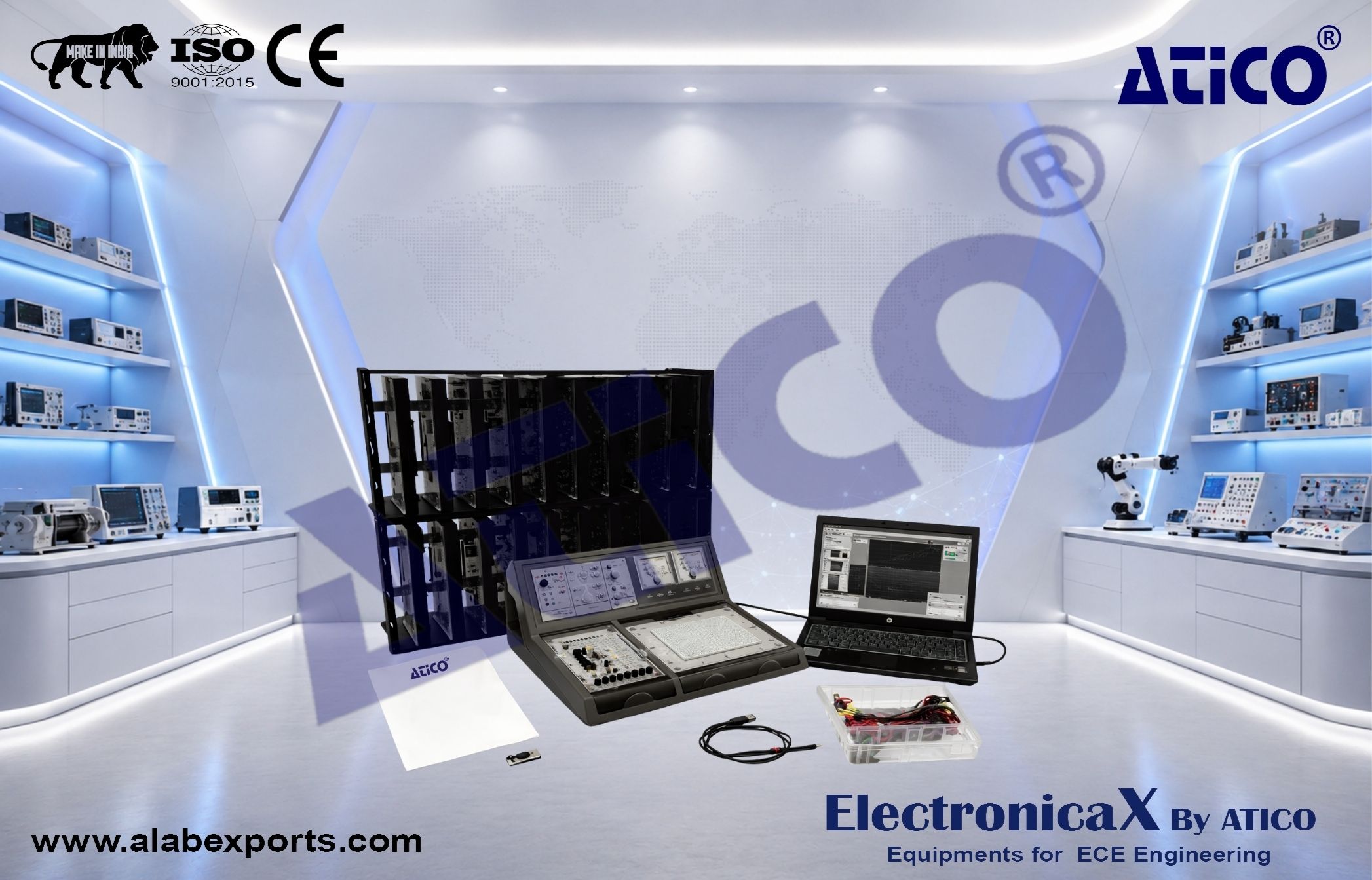
Main Unit :
DC Power Supply :
-
Output voltage: °5V, °12V
-
Protection: Overload protection
AC Power Supply :
-
Output voltage: 9V–0–9V
-
Protection: Overload protection
Signal Generator :
-
Frequency range: 1 Hz to 100 kHz (adjustable)
-
Waveforms: Sine, square, triangle
-
Pulse output: TTL level
Function Generator :
- Waveforms: Sine, square
- Frequency range: 1 Hz to 100 kHz
Output amplitude:
- –18 V peak-to-peak (open circuit)
- –9 V peak-to-peak (with load)
Measuring Instruments :
- 3° digit digital voltmeter and ammeter
- DC voltage range: 2V, 20V
- Accuracy: °0.3% of reading + 1 digit
- DC current range: 200 °A, 200 mA
- Accuracy: °0.3% + 1 digit
Galvanometer :
Additional Components :
- LED indicators (10 LEDs for logic state display)
- 7-segment digital display with decoder and input switches
- Breadboard (1680 tie points) for circuit prototyping
Module Categories
Basic Electricity Modules :
- Basic electrical devices
- Fundamental electricity experiments
- Sensor-based experiments
Electronic Circuit Modules :
- Diode, clipping, and clamping circuits
- Rectifier, differentiator, and integrator circuits
- Transistor amplifier circuits
- Multistage amplifier circuits
- Field-effect transistor circuits
- Operational amplifier circuits (multiple configurations)
Digital Logic Modules :
- Combination logic circuits
- Sequential logic circuits
Motor Control Modules (Optional) :
- Low voltage control systems
- Single-phase motor modules
- Capacitor motor systems
- Supporting transformer module
Experiments
Basic Electricity :
- Electrical measurements
- Potentiometer characteristics
- DC and AC voltage/current measurement
- Resistance measurement
- Kirchhoff–s laws
- Wheatstone bridge
- Maximum power transfer theorem
- Circuit analysis (DC and AC)
- RC, RL, RLC circuits
- Series-parallel circuits
- Transient response and time constants
Electronic Circuits :
- Diode and Zener diode characteristics
- LED and photodiode characteristics
- Rectifier circuits
- Clipping and clamping circuits
- RC integrator and differentiator
- Transistor characteristics
- Amplifier configurations (CE, CB, CC)
- FET and MOSFET circuits
- Feedback amplifiers
Digital Logic :
- Logic gates (AND, OR, NOT, NAND, NOR, XOR)
- Logic gate applications
- Boolean algebra
- Karnaugh maps
- Flip-flops (RS, JK, D, T)
- Counters and shift registers
- Multiplexers and demultiplexers
- Adders and subtractors
- Encoders and decoders
Motor Experiments (Optional) :
- Motor control circuits
- Forward and reverse operation
- Speed control
- Overload protection
Virtual Laboratory (V-LAB) :
- 3D interactive virtual lab environment
- Measurement tools including digital multimeter and oscilloscope
- Virtual breadboard for circuit simulation
- Experiment playback and recording
- Data saving functionality
Computer-Based Training :
- Built-in circuit simulation
- Fault simulation capability
- Comparison between simulated and actual results
- Support for virtual instruments
System Requirements for Virtual Lab :
- Operating System: Windows 10 or later
- Processor: Equivalent to modern multi-core processor
- Memory: 8 GB RAM or higher
- Storage: Solid-state drive recommended
- Graphics: Dedicated graphics support recommended