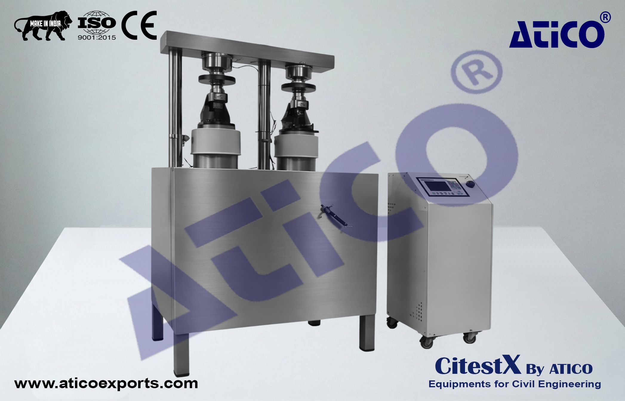
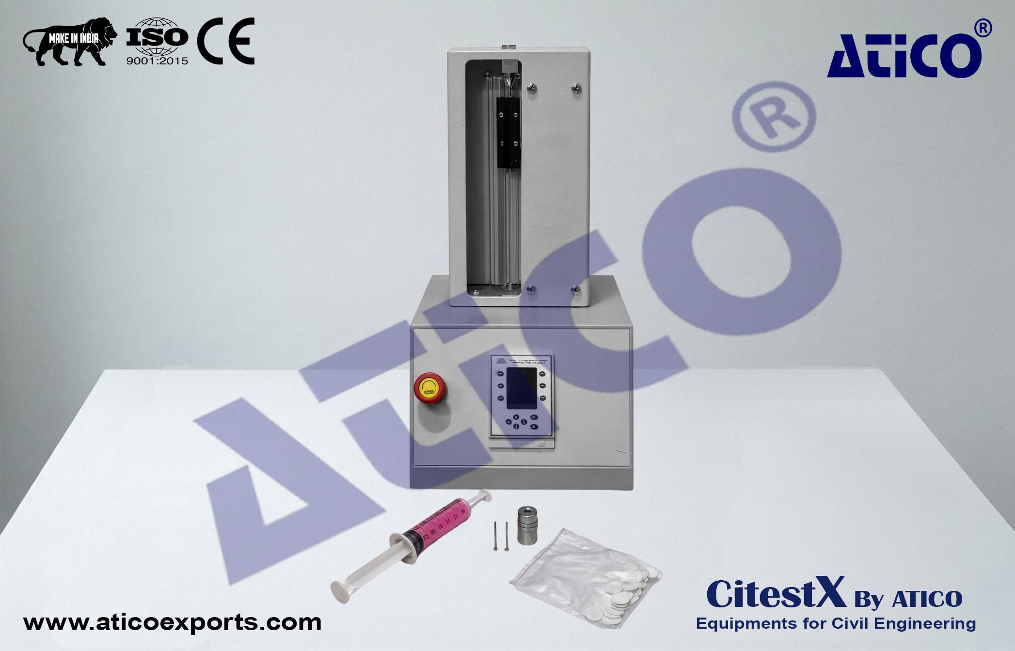
The Automatic Cement Compression and Flexure Testing Machine has been designed for testing the flexural strength of 40 ° 40 ° 160 mm prisms and the compression strength of the broken prism halves (40 ° 40 mm), as well as 50 ° 50 mm and 70.7 mm mortar cubes.
The machines are manufactured to meet CE norms for safety and health operator requirements.
Compression and flexure jigs, distance pieces, and removable transparent front–rear safety doors (for high-force testing) should be ordered separately.
Operating Concept :
Automatic Cement Compression and Flexural Testing Machines allow experienced operators to perform tests with minimum preparation.
The fully integrated operator system allows:
- Setting test parameters, including pace rate (if required)
- Selecting compression or flexure frame by valve
- Choosing frame capacity (for load calibration values)
- Selecting load cell with selector switch (up/down)
- Starting the test with START button
- Automatic rapid approach of piston
- Automatic test termination after specimen failure
- Automatic saving of test parameters and results
System Components :
Automatic Cement Compression and Flexural Testing Machines consist of :
- Very rigid two-column single or double chamber load frames
- Automatic Hydraulic Power Pack
- Digital Data Acquisition & Control System
- Upper platen with ball seating assembly
- Lower platen
- Loading cylinder assembly with limit switch for safety
- Software and Ethernet cable
Cement Compression & Flexural Load Frames :
- 15 kN and 250 kN high-quality load cells are used on frames to ensure high accuracy and sensitivity.
- Both frames are fitted with °165 mm round platens, suitable for flexure and compression jigs.
Upper Platens :
- Manufactured from high-quality hardened steel (– HRC 53), ground and polished.
- Surface roughness of machine and auxiliary platens: – 3.2 °m.
Distance Pieces :
- Due to modular frame design, samples with different sizes, loads, and pace rates can be tested on - both chambers using appropriate distance pieces.
Loading Cylinder Assembly & Limit Switch :
- All frames have a single-acting upstroke ram.
- Piston diameter changes according to capacity.
- Maximum ram stroke: 50 mm
- A limit switch cuts pump power at maximum stroke
- Low-friction PTFE seal between piston and cylinder
HYDRAULIC POWER PACK AND DIGITAL DATA ACQUISITION & CONTROL SYSTEM :
Hydraulic Power Pack :
- Automatic hydraulic power pack, dual-stage, controlled by digital readout and control unit, designed to supply required oil to load frames.
- Pace rate: 0.05 – 2.4 kN/sec
- Accuracy: °5%
- Rapid approach pump: standard
- Safety valve: prevents overload
Dual Stage Pump :
Two pumping stages :
- Low-pressure gear pump (rapid approach)
- High-pressure radial piston pump (testing)
- Rapid approach significantly reduces test preparation time.
Motor :
- AC motor with inverter control
- Flow variation achieved via motor speed change
- Maximum system pressure: 400 bar
Distribution Block :
Controls oil flow using :
- Solenoid valve
- Safety valve (max pressure valve)
- Pressure transducer
- Low-pressure gear pump
- High-pressure piston pump
Load Cell :
- High-accuracy 15 kN and 250 kN load cells used.
- Excellent resolution at very low loads
(Class 1 from 2.5 kN to 250 kN)
Oil Tank :
- Capacity: 25 liters
- Hydraulic oil ISO VG 46 recommended
Digital Readout and Control Unit :
- Controls machine operation and processes data from load cells and pressure transducers.
- LCD display with function keys
- Menu-driven operation
- Real-time graphical display:
- Load vs Time
- Stress vs Time
- Digital graphic display of loading rate
Software :
- Entry of sample, company, laboratory, and test data
- Load-time graphs and test reports
- Data storage and printout