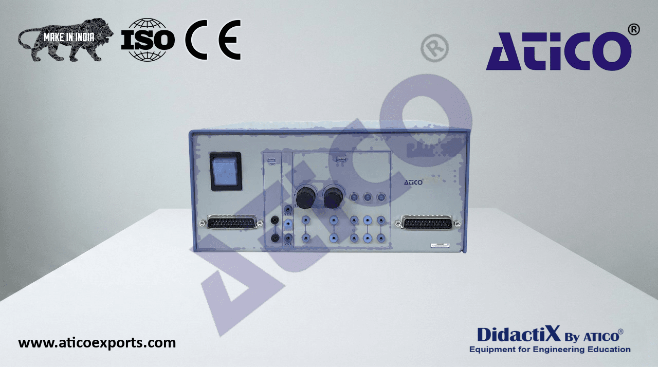
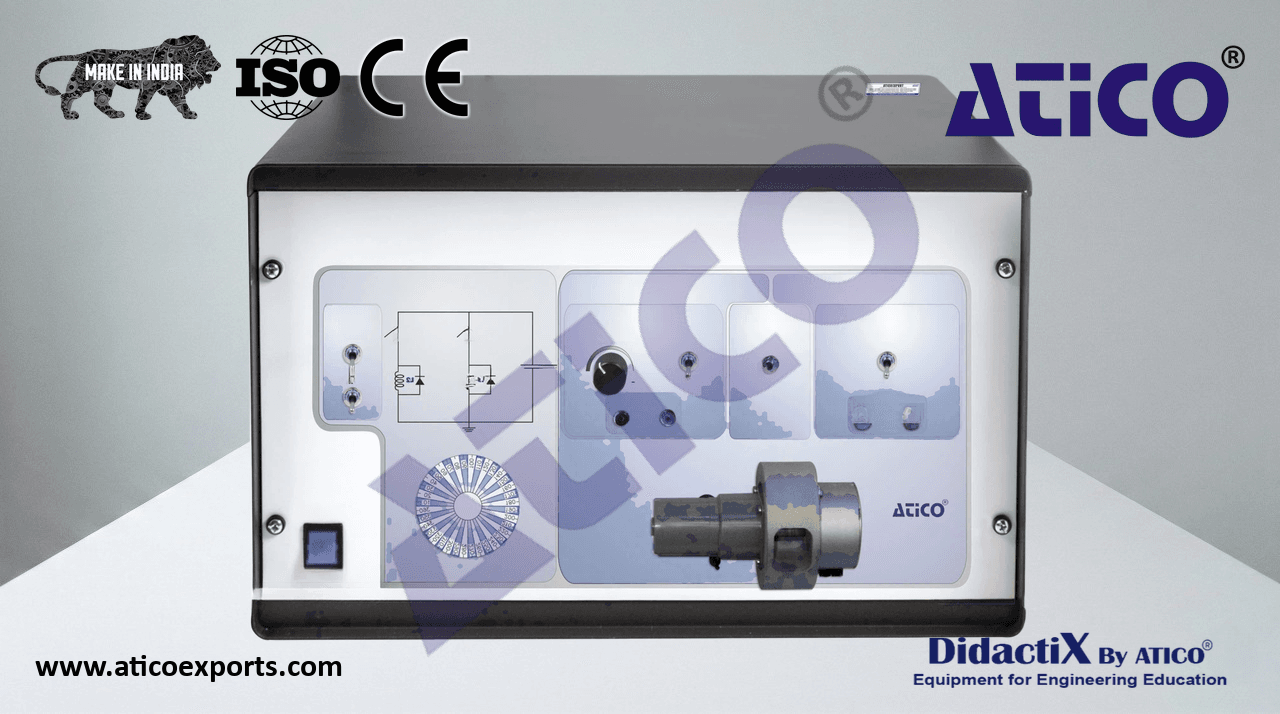
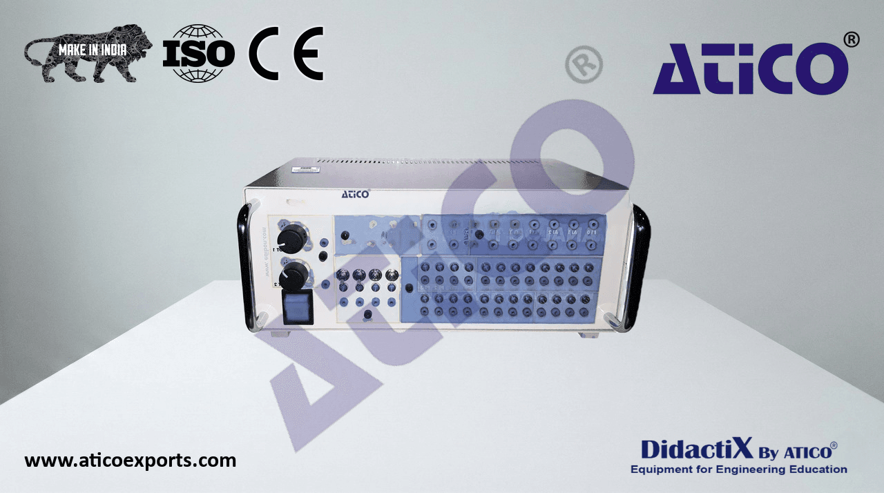
ATENG 12388 — Computer Controlled Advanced Power Electronics Application
(for main items)
- With this unit there are several options and possibilities:
- Main items: 1, 2, 3 and 4.
- Optional items: 5, 6 and 7.
- Let us describe first the main items (1 to 4):
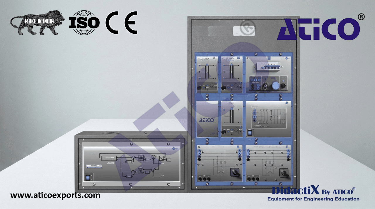
- 1AE-PEC Application.
- N-ALI01. Industrial Main Power Supply Module.
- Supply voltage: 400 VAC, 3PH + N.
ON / OFF removable key.
- Output voltage connections:
- Three-Phase + Neutral: 400 VAC.
- Single-Phase: 230 VAC.
- Three-Phase supply hose with IP44 3PN + E 32 A 400 V connecting plug.
- Differential magnetothermal 4 poles, 25 A, 300 mA AC 6 KA.
Emergency stop push-button.
- N-ALI05. Fixed Voltage Supply Module 12+12 VAC and +5 VDC.
- AC Output: 12-0-12 VAC, 10 A.
- DC Output: 5 V, 3 A.
- N-ALI06. Fixed Voltage Supply Module 18+18 VAC and ±15 VDC.
- AC Output: 18-0-18 VAC, 10 A.
- DC Output: ±15 V, 2 A.
- N-ALI07. Fixed Voltage Supply Module 18+18 VAC and adjustable from 0 to 30 VDC.
- AC Output: 18-0-18 VAC, 10 A.
- DC Output: adjustable 0-30 V, 2 A.
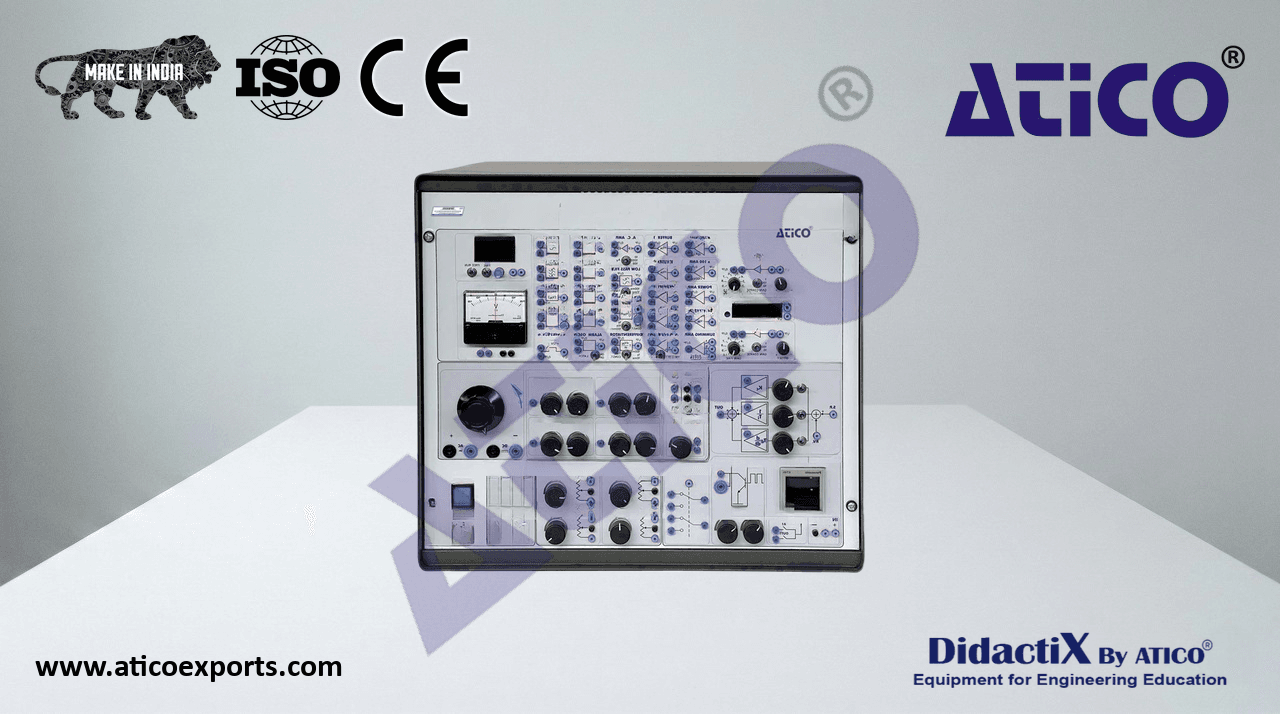
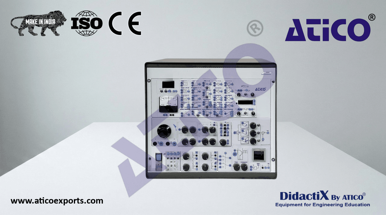
- N-SCN. Voltage and Current Monitoring Module with Converter Control.
- Voltage Reference Generator:
- Range of continuous regulation reference signal: from -10 V to +10 V, from 0 to +10 V.
- Range of step reference signal: from -10 V to +10 V, from 0 to +10 V.
- Switch for selecting voltage range: between the 0 / ±10 V range and the 0 / +10 V range.
- Two Pulse Control Unit:
- Control voltage (U_c): 0 V to 10 V.
- Trigger angle: 180° to 0°.
- Number of outputs: 2 x 2.
- Inhibit voltage (U_INH): 15 V (open): Trigger pulses, 0 V: no trigger pulses.
- Six Pulse Control Unit:
- Control voltage (U_c): 0 to 10 V.
- Trigger angle: 180° to 0° (300°.120° / 60°.240°):
- Number of outputs: 3 x 2.
- Inhibit voltage (U_INH): 15 V (open): Trigger pulses, 0 V: no trigger pulses.
- PWM, Control Unit:
- Control voltage (U_c): 0 to 10 V.
- PWM: 20-200 Hz / 0.2-2 kHz / 2-20 kHz.
- Duty cycle (D): ton / T = 0-0.95.
- Number of outputs: 2 x 2, with LED indication of status.
- Output amplifier: Threshold voltage 5 V, short-circuit proof.
- Inhibit voltage (U_INH): 15 V (open): Trigger pulses, 0 V: ionger pulses at certain outputs only.
- Run-up Control Unit:
- Input signal range (U_i): -10 V to +10 V.
- Slew-rate fine adjustment: 0.5 to 50 V / s.
- Voltage gain fine adjustment: 0.1 to 1.
- Inhibit voltage (U_INH): 0 V: Zero output voltage, 15 V: normal operation.
- PID Controller:
- Signal voltage range: -10 V to +10 V.
- Controller parameters: Continuously adjustable.
- Proportional gain (K_p): 0 to 1000.
- Integral Time (T_I): 1 ms to 100s.
- Derivative Time (T_D): 0.2 ms to 20s.
- Integral controller reset input: Available.
- Error signal measurement terminal: Available.
7
Complete Technical Specifications (for main items)
- Voltage and Current Measurement Modules for Data Acquisition:
- Voltage-to-voltage gain: 0.01 V / V.
- Current-to-voltage gain: 0.1 V / A.
- Gain and Offset Adjust:
- Input signal voltage interval: -50 V to +50 V.
- Adjustable gain level: 0 to 1, 0 to 10, 0 to 100.
- Pulse signal attenuation: Available.
- Time constants: 0.1 to 10 ms; 10 to 100 ms.
- Offset voltages: -10 V to +10 V.
- Coarse setting: Through rotary switches.
- Fine setting: Through potentiometer.
- Data Acquisition Module: NI PCIe-6321:
- Sample time: 250 Ksps.
- Resolution: 16-bit.
- Number of input channels: 16.
- Number of output channels: 2.
- Required elements (at least one) (Not included):
DCDC-KIT. DC/DC Conversion Kit.
- N-DCDC/I. Isolated DC/DC Conversion Module.
- Main input: one phase, fixed.
- Transformer ratio 1:1.
- Input and output with 16 A fuses.
- N-DCDC/2T. DC/DC Conversion Module with 2 Transistors.
One branch of 2 transistors.
- Used semiconductor: IGBT:
- Collector-Emitter Voltage (V_CE): 600 V.
- Continuous Collector Current (I_C): 24 A at T_C = 25 °C
- Collector-Emitter Saturation Voltage (V_CEsat): 1.8 V typical at I_C =15 A.
- Gate-Emitter Voltage (V_GE): ±20 V.
- Power handling capacity: Up to 3 kW.
Internal IGBT driver.
Inductive loads supported (internal snubber in each transistor).
One 33 µH inductor with current sensor for closed-loop control.
One 1000 µF capacitor with voltage sensor for closed-loop control.
- Input and output with 16 A fuses.
- N-DCDC/TD. DC/DC Conversion Module with Transistor and Diode.
One branch of one transistor and one diode.
- Used semiconductor: IGBT and diode:
IGBT
- Collector-Emitter Voltage (V_CE): 600 V.
- Continuous Collector Current (I_C): 24 A at T_C = 25 °C.
- Collector-Emitter Saturation Voltage (V_CEsat): 1.8 V typical at I_C =15 A.
- Gate-Emitter Voltage (V_GE): ±20 V.
- Power handling capacity: Up to 3 kW.
DIODE
- Direct Average Current (I_FAV): 12 A.
- Direct Non-Repetitive Overload Current (I_FSM): 75A (tp = 10 ms).
- Repetitive Peak Reverse Voltage (V_RRM): 1000 V.
- Recovery Reverse Time (t_rr): 65 ns max.
- Power handling capacity: Up to 3 kW.
Internal IGBT driver.
Inductive loads supported (internal snubber in parallel with transistor).
One 33 µH inductor with current sensor for closed-loop control.
One 1000 µF capacitor with voltage sensor for closed-loop control.
- Input and output with 16 A fuses.
- N-IGBT. IGBT Transistor Module.
- Collector-Emitter Voltage (V_CE): 600 V.
- Continuous Collector Current (I_C): 24 A at T_C = 25 °C.
- Collector-Emitter Saturation Voltage (V_CEsat): 1.8 V typical at I_C =15 A.
- Gate-Emitter Voltage (V_GE): ±20 V.
- Power handling capacity: Up to 3 kW.
- Input and output with 16 A fuses.
8
Complete Technical Specifications (for main items)
- N-BJT. BJT Transistor Module.
- Collector Current (I_c): 2.5 A.
- Collector-Emitter Voltage (V_CE): 30 V.
- Power handling capacity: Suitable for low-power triggering applications.
- Input and output with 16 A fuses.
- N-MOSFET. MOSFET Transistor Module.
- Drain-Source Voltage (V_DS): 400 V.
- Continuous Drain Current (I_D): 10 A.
- Drain-Source On-State Resistance (R_DS(on)): 0.55Ω.
- Gate-Source Voltage (V_GS): ±20 V.
- Power handling capacity: Up to 3 kW.
- Input and output with 16 A fuses.
- N-DTS. DIAC, TRIAC and SCR Module.
- SCR (Silicon Controlled Rectifier):
- Direct Average Current (I_TAV): 7.6 A max.
- True RMS Value of the Direct Current (I_TRMS): 12 A.
- Max. Repetitive Reverse Voltage (V_RRM): 800 V.
- Trigger Current (I_GT): 15 mA max.
- Trigger Voltage (V_GT): 1.5 V max.
- Power handling capacity: Up to 3 kW.
- DIAC (Diode for Alternating Current):
- Breakover Voltage (V_BO): 30 V to 40 V.
- Repetitive Peak On-State Current (I_TSM): 2 A.
- Power handling Capacity: Suitable for triggering TRIACs in low-power applications.
- TRIAC (Triode for Alternating Current):
- True RMS Value of the Direct Current (I_TAV): 8 A max.
- Non-Repetitive Peak Current (I_TSM): 70 A (50 Hz), 77A (60 Hz).
- Max. Repetitive Reverse Voltage (V_DRM): 800 V.
- Trigger Current (I_GT): 25 mA max. (all quadrants).
- Trigger Voltage (V_GT): 2.5 V max.
- State Keeping Current (I_H): 25 mA max.
- Power handling capacity: Up to 3 kW.
- Required elements (at least one) (Not included):
- N-REF. Single Phase Fixed Resistor Module.
- Resistor value: 150 Ohm.
- Maximum power: 500 W.
- Selector:
- Position 0: Circuit opened.
- Position 1: Circuit closed.
- Fuse: 2 A.
- N-REV. Single-Phase Variable Resistor Module. Variable resistor of 150 Ohm.
- Maximum power: 500 W.
Potentiometer.
- Terminals:
Three terminals to choose all resistance or variable resistance.
- Fuse: 2 A.
ACDC/C-KIT. AC/DC Conversion Kit with Controlled Rectification.
- N-ACDC/U. AC/DC Conversion Module with Uncontrolled Rectification.
- Direct Average Current (I_FAV): 12 A.
- Direct Non-Repetitive Overload Current (I_FSM): 75 A (tp = 10 ms).
- Repetitive Peak Reverse Voltage (V_RRM): 1000 V.
- Recovery Reverse Time (t_rr): 65 ns max.
- Power handling capacity: Up to 3 kW.
- N-CAP. Capacitor Module.
- Rated value: 2 x 1000 µF.
- Rated voltage: 385 V.
- Polarity inversion protection: Available.
- Discharge resistance: 330 kΩ (t = 330s).
9
Complete Technical Specifications (for main items)
- Required elements (at least one) (Not included):
- N-REF. Single Phase Fixed Resistor Module.
- Resistor value: 150 Ohm.
- Maximum power: 500 W.
- Selector:
- Position 0: Circuit opened.
- Position 1: Circuit closed.
- Fuse: 2 A.
- N-REV. Single-Phase Variable Resistor Module.
Variable resistor of 150 Ohm.
- Maximum power: 500 W.
Potentiometer.
- Terminals:
Three terminals to choose all resistance or variable resistance.
- Fuse: 2 A.
- N-IND. Single-phase Inductance Module.
- Inductance: 1.4 H.
- Switch:
- Position 0: Circuit opened.
- Position 1: Circuit closed.
- Fuse: 2 A.
ACDC/C-KIT. AC/DC Conversion Kit with Controlled Rectification.
- N-ACDC/C. AC/DC Conversion Module with Controlled Rectification.
- Direct Average Current (I_TAV): 7.6 A max.
- True RMS Value of the Direct Current (I_TRMS): 12 A.
- Max. Repetitive Reverse Voltage (V_RRM): 800 V.
- Trigger Current (I_GT): 15 mA max.
- Trigger Voltage (V_GT): 1.5 V max.
- Power handling capacity: Up to 3 kW.
- N-HT. Heater Module with Temperature Sensor.
- Resistance: 150Ω / 500 W.
- Temperature sensor: PT100:
- Temperature range: -50 to +500 °C.
- Internally conditioned to 0.05 V / °C.
- Output voltage from 0 to 10 V.
- Max. measurable temperature: 200 °C.
- N-LAM36. 24 V 15 W Lamp Module.
- Nominal voltage: 24 VAC.
- Consumption: 15 W.
- Required elements (at least one) (Not included):
- N-REF. Single Phase Fixed Resistor Module.
- Resistor value: 150 Ohm.
- Maximum power: 500 W.
- Selector:
- Position 0: Circuit opened.
- Position 1: Circuit closed.
- Fuse: 2 A.
- N-REV. Single-Phase Variable Resistor Module.
- Variable resistor: 150 Ohm.
- Maximum power: 500 W.
Potentiometer.
- Terminals:
Three terminals to choose all resistance or variable resistance.
- Fuse: 2 A.
- N-IND. Single-phase Inductance Module.
- Inductance: 1.4 H.
- Switch:
- Position 0: Circuit opened.
- Position 1: Circuit closed.
- Fuse: 2 A.
10
Complete Technical Specifications (for main items)
N-DCAC. Single-phase and Three-phase AC/DC Conversion Module.
One-phase and three-phase DC-to-AC conversion supported.
- Used semiconductor: IGBT:
- Collector-Emitter Voltage (V_CE): 600 V.
- Continuous Collector Current (I_C): 24 A at T_C = 25 °C.
- Collector-Emitter Saturation Voltage (V_CEsat): 1.8 V typical at I_C =15 A.
- Gate-Emitter Voltage (V_GE): ±20 V.
- Power handling capacity: Up to 3 kW.
- Number of semiconductors: 6.
Internal IGBT driver.
Inductive loads supported (internal snubber in each transistor).
- Input and output with 16 A fuses.
- Required elements (at least one) (Not included):
- N-REFT. 3PH Commutable Resistor Load Module.
- Nominal voltage: 400 VAC.
- Three-phase resistance: 3 x 150 Ohm.
- Nominal current: 1.6 A.
Manual switch to turn activate/deactivate resistors.
- Fuses: 3 x 2 A.
- Terminals:
Four input terminals (3PH + N).
Four output terminals (3PH + N).
- N-INDT. Three-phase Commutable Inductive Load Module.
- Nominal voltage: 400 VAC.
- Inductance: 1.4 H.
- Nominal current: 1.6 A.
Manual switch to turn activate/deactivate inductances.
- Fuses: 3 x 2 A.
- Terminals:
Four input terminals (3PH + N).
Four output terminals (3PH + N).
ACAC-KIT. AC/AC Conversion Kit.
- N-ACAC. AC/AC Conversion Module with Dual Time Constant.
- Used semiconductors: DIAC and TRIAC:
- DIAC (Diode for Alternating Current):
- Breakover Voltage (V_BO): 30 V to 40 V.
- Repetitive Peak On-State Current (I_TSM): 2 A.
- Power handling capacity: Suitable for triggering TRIACs in low-power applications.
- TRIAC (Triode for Alternating Current):
- True RMS Value of the Direct Current (I_TAV): 8 A max.
- Max. Repetitive Reverse Voltage (V_DRM): 800 V.
- Trigger Current (I_GT): 25 mA max. (all quadrants).
- Trigger Voltage (V_GT): 2.5 V max.
- State Keeping Current (I_H): 25 mA max.
- Power handling capacity: Up to 3 kW.
- Variable to control: Amplitude.
- Used technology: Double time constant.
- Input and output with 16 A fuses.
- N-DTS. DIAC, TRIAC and SCR Module.
- SCR (Silicon Controlled Rectifier):
- Direct Average Current (I_TAV): 7.6 A max.
- True RMS Value of the Direct Current (I_TRMS): 12 A.
- Max. Repetitive Reverse Voltage (V_RRM): 800 V.
- Trigger Current (I_GT): 15 mA max.
- Trigger Voltage (V_GT): 1.5 V max.
- Power handling capacity: Up to 3 kW.
- DIAC (Diode for Alternating Current):
- Breakover Voltage (V_BO): 30 V to 40 V.
- Repetitive Peak On-State Current (I_TSM): 2 A.
- Power handling capacity: Suitable for triggering TRIACs in low-power applications.
- TRIAC (Triode for Alternating Current):
- True RMS Value of the Direct Current (I_TAV): 8 A max.
- Non-Repetitive Peak Current (I_TSM): 70A (50 Hz), 77A (60 Hz).
- Max. Repetitive Reverse Voltage (V_DRM): 800 V.
- Trigger Current (I_GT): 25 mA max. (all quadrants).
- Trigger Voltage (V_GT): 2.5 V max.
- State Keeping Current (I_H): 25 mA max.
- Power handling capacity: Up to 3 kW.
11
Complete Technical Specifications (for main items)
- N-LAM08. Two Lamp-holders + Incandescent Lamps Module.
- Nominal voltage: 230 VAC (PH + N).
- Two bulbs:
- Consumption: 40 W each.
Two terminals each one.
- Required elements (at least one) (Not included):
- N-REF. Single Phase Fixed Resistor Module.
- Resistor value: 150 Ohm.
- Maximum power: 500 W.
- Selector:
- Position 0: Circuit opened.
- Position 1: Circuit closed.
- Fuse: 2 A.
- N-REV. Single-Phase Variable Resistor Module.
Variable resistor of 150 Ohm.
- Maximum power: 500 W.
Potentiometer.
- Terminals:
Three terminals to choose all resistance or variable resistance.
- Fuse: 2 A.
- N-IND. Single-phase Inductance Module.
- Inductance: 1.4 H.
- Switch:
- Position 0: Circuit opened.
- Position 1: Circuit closed.
- Fuse: 2 A.
ACDCAC-KIT. AC/DC/AC Conversion Kit (Frequency or Cycle Converter).
- N-ACDC/U. AC/DC Conversion Module with Uncontrolled Rectification.
- Direct Average Current (I_FAV): 12 A.
- Direct Non-Repetitive Overload Current (I_FSM): 75 A (tp = 10 ms).
- Repetitive Peak Reverse Voltage (V_RRM): 1000 V.
- Recovery Reverse Time (t_rr): 65 ns max.
- Power handling capacity: Up to 3 kW.
- N-DCAC. Single-phase and Three-phase AC/DC Conversion Module.
One-phase and three-phase DC-to-AC conversion supported
- Used semiconductor: IGBT:
- Collector-Emitter Voltage (V_CE): 600 V.
- Continuous Collector Current (I_C): 24 A at T_C = 25 °C.
- Collector-Emitter Saturation Voltage (V_CEsat): 1.8 V typical at I_C =15 A.
- Gate-Emitter Voltage (V_GE): ±20 V.
- Power handling capacity: Up to 3 kW.
- Number of semiconductors: 6.
Internal IGBT driver.
Inductive loads supported (internal snubber in each transistor).
- Input and output with 16 A fuses.
- N-CAP. Capacitor Module.
- Rated value: 2 x 1000 µF.
- Rated voltage: 385 V.
- Polarity inversion protection: Available.
- Discharge resistance: 330 kΩ (t = 330s).
- Required elements (at least one) (Not included):
- N-REFT. 3PH Commutable Resistor Load Module.
- Nominal voltage: 400 VAC.
- Three-phase resistance: 3 x 150 Ohm.
- Nominal current: 1.6 A.
Manual switch to turn activate/deactivate resistors.
- Fuses: 3 x 2 A.
- Terminals:
Four input terminals (3PH + N).
Four output terminals (3PH + N).
12
Complete Technical Specifications (for main items)
- N-INDT. Three-phase Commutable Inductive Load Module.
- Nominal voltage: 400 VAC.
- Inductance: 1.4 H.
- Nominal current: 1.6 A.
Manual switch to turn activate/deactivate inductances.
- Fuses: 3 x 2 A.
- Terminals:
Four input terminals (3PH + N).
Four output terminals (3PH + N).
- CCR-DCM-KIT. AC/DC Conversion Kit with Controlled Rectification and DC/DC: DC Motor Control.
- N-ACDC/C. AC/DC Conversion Module with Controlled Rectification.
- Direct Average Current (I_TAV): 7.6 A max.
- True RMS Value of the Direct Current (I_TRMS): 12 A.
- Max. Repetitive Reverse Voltage (V_RRM): 800 V.
- Trigger Current (I_GT): 15 mA max.
- Trigger Voltage (V_GT): 1.5 V max.
- Power handling capacity: Up to 3 kW.
A diode to connect in parallel and inverse for inductive loads.
- N-DCDC/TD. DC/DC Conversion Module with Transistor and Diode.
One branch of one transistor and one diode.
- Used semiconductor: IGBT and diode:
IGBT
- Collector-Emitter Voltage (V_CE): 600 V.
- Continuous Collector Current (I_C): 24 A at T_C = 25 °C.
- Collector-Emitter Saturation Voltage (V_CEsat): 1.8 V typical at I_C =15 A.
- Gate-Emitter Voltage (V_GE): ±20 V.
- Power handling capacity: Up to 3 kW.
DIODE
- Direct Average Current (I_FAV): 12 A.
- Direct Non-Repetitive Overload Current (I_FSM): 75 A (tp = 10 ms).
- Repetitive Peak Reverse Voltage (V_RRM): 1000 V.
- Recovery Reverse Time (t_rr): 65 ns max.
- Power handling capacity: Up to 3 kW.
Internal IGBT driver.
Inductive loads supported (internal snubber in parallel with transistor).
One 33 µH inductor with current sensor for closed-loop control.
One 1000 µF capacitor with voltage sensor for closed-loop control.
- Input and output with 16 A fuses.
- N-DCDC/H. DC/DC Conversion Module with H-Bridge.
H Bridge to control the polarity and the amplitude of the DC voltage.
- Used semiconductor: IGBT:
- Collector-Emitter Voltage (V_CE): 600 V.
- Continuous Collector Current (I_C): 24 A at T_C = 25 °C.
- Collector-Emitter Saturation Voltage (V_CEsat): 1.8 V typical at I_C =15 A.
- Gate-Emitter Voltage (V_GE): ±20 V.
- Power handling capacity: Up to 3 kW.
- Number of semiconductors: 4.
Internal IGBT driver.
Inductive loads supported (internal snubber in each transistor).
- Input and output with 16 A fuses.
- EMT24. 12 VDC Motor.
- Nominal power: 120 W.
- Rated voltage: 12 V.
- Speed: 10000 rpm.
- Rated current: 10 A.
- Shaft height: 71 mm.
- EMT5. DC Shunt/Series/Compound Excitation Motor-Generator.
- Nominal power: 300 W.
- Armature voltage: 200 VDC.
- Excitation voltage: 230 VDC.
- Armature current: 1.5 A.
- Excitation current: 0.4 A.
- Speed: 3400 / 7500 rpm.
- Shaft height: 71 mm.
13
Complete Technical Specifications (for main items)
- OPTS. Optical Sensor with 2500 Pulses per Revolution.
- Speed range: 0 – 6000 rpm.
- Accuracy class: 1.5.
- Resolution: 2500 pulses per revolution and position detection.
- Power supply: 5 V.
- C-ACM-KIT. AC/DC/AC Conversion Kit: Three-Phase AC Motor Control.
- N-ACDC/U. AC/DC Conversion Module with Uncontrolled Rectification.
- Direct Average Current (I_FAV): 12 A.
- Direct Non-Repetitive Overload Current (I_FSM): 75 A (tp = 10 ms).
- Repetitive Peak Reverse Voltage (V_RRM): 1000 V.
- Recovery Reverse Time (t_rr): 65 ns max.
- Power handling capacity: Up to 3 kW.
- N-DCAC. Single-phase and Three-phase AC/DC Conversion Module.
One-phase and Three-phase DC-to-AC conversion supported.
- Used semiconductor: IGBT:
- Collector-Emitter Voltage (V_CE): 600 V.
- Continuous Collector Current (I_C): 24A at T_C = 25 °C.
- Collector-Emitter Saturation Voltage (V_CEsat): 1.8 V typical at I_C =15 A.
- Gate-Emitter Voltage (V_GE): ±20 V.
- Power handling capacity: Up to 3 kW.
- Number of semiconductors: 6.
Internal IGBT driver.
Inductive loads supported (internal snubber in each transistor).
- Input and output with 16 A fuses.
- N-CAP. Capacitor Module.
- Rated value: 2 x 1000 µF.
- Rated voltage: 385 V.
- Polarity inversion protection: Available.
- Discharge resistance: 330 kΩ (t = 330s).
- EMT17. 3PH Squirrel-Cage Motor with “Y” connection.
- Nominal power: 370 W.
- Nominal voltage: 3 x 400 VAC Y.
- Frequency: 50/60 Hz.
- Number of poles: 2.
- Speed: 2730 rpm.
- Nominal current: 0.97 A.
- Shaft height: 71 mm.
- OPTS. Optical Sensor with 2500 Pulses per Revolution.
- Speed range: 0 – 6000 rpm.
- Accuracy class: 1.5.
- Resolution: 2500 pulses per revolution and position detection.
- Power supply: 5 V.
- All necessary cables to realize the practical exercises are included.
- The complete unit includes as well:
Advanced Real-Time SCADA.
Open Control + Multicontrol + Real-Time Control.
Specialized Control Software based on LabVIEW.
Projector and/or electronic whiteboard compatibility allows the unit to be explained and
demonstrated to an entire class at one time.
Capable of doing applied research, real industrial simulation, training courses, etc.
Remote operation and control by the user, as well as remote support from technical
support, are always included.
Totally safe, utilizing 4 safety systems (Mechanical, Electrical, Electronic & Software).
Designed and manufactured under several quality standards.
Optional ICAI software to create, edit and carry out practical exercises, tests, exams,
calculations, etc. Apart from monitoring user's knowledge and progress reached.
This unit has been designed for future expansion and integration. A common expansion is
the Scada-Net (ESN) System which enables multiple students to simultaneously
operate many units in a network.
14
Complete Technical Specifications (for main items)
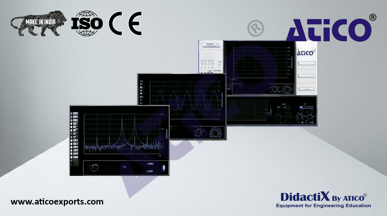
- 2 AE-PEC/CCSOF. Computer Control + Data Acquisition + Data Management Software:
The three softwares are part of the SCADA system.
Compatible with actual Windows operating systems. Graphic and intuitive simulation of the process in
screen. Compatible with the industry standards.
Registration and visualization of all process variables in an automatic and simultaneous way.
Flexible, open and multicontrol software, developed with actual windows graphic systems, acting
simultaneously on all process parameters.
Management, processing, comparison and storage of data.
It allows the registration of the alarms state and the graphic representation in real time.
Comparative analysis of the obtained data, after the process and modification of the conditions during
the process.
AE-PEC/CCSOF
Open software, allowing the teacher to modify texts, instructions. Teacher’s and student’s
passwords to facilitate the teacher’s control on the student, and allowing the access to different work
levels.
This unit allows the 30 students of the classroom to visualize simultaneously all the results
and the manipulation of the unit, during the process, by using a projector or an electronic
whiteboard.
3 Cables and Accessories, for normal operation.
- 4Manuals:
- This unit is supplied with 7 manuals: Required services, Assembly and Installation, Control Software, Starting-up, Safety, Maintenance
& Practices manuals.
- References 1 to 4 are the main items: ATENG 12388 + AE-PEC/CCSOF + Cables and Accessories + Manuals are included in the minimum
supply for enabling normal and full operation.
15