ATENG 12119 — Free & Forced Vibration Unit
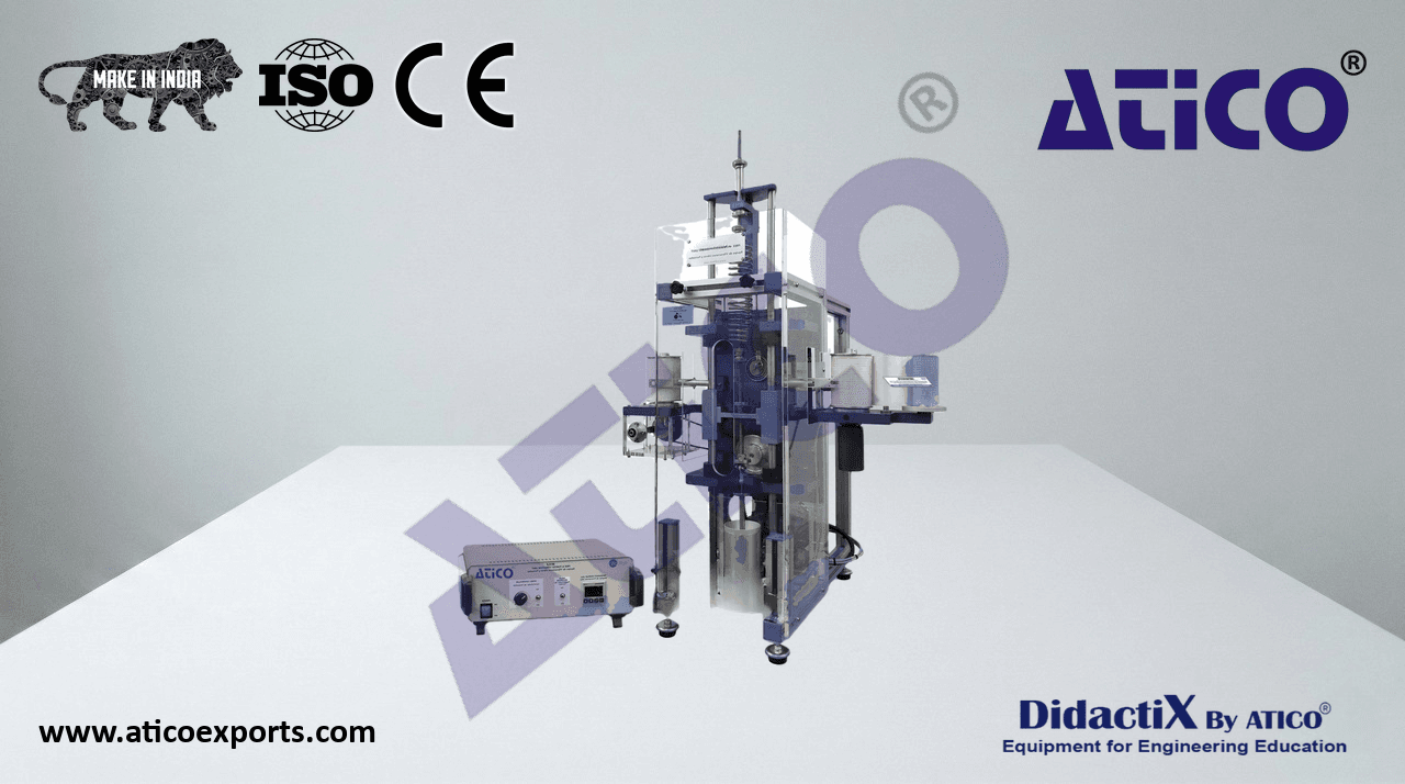
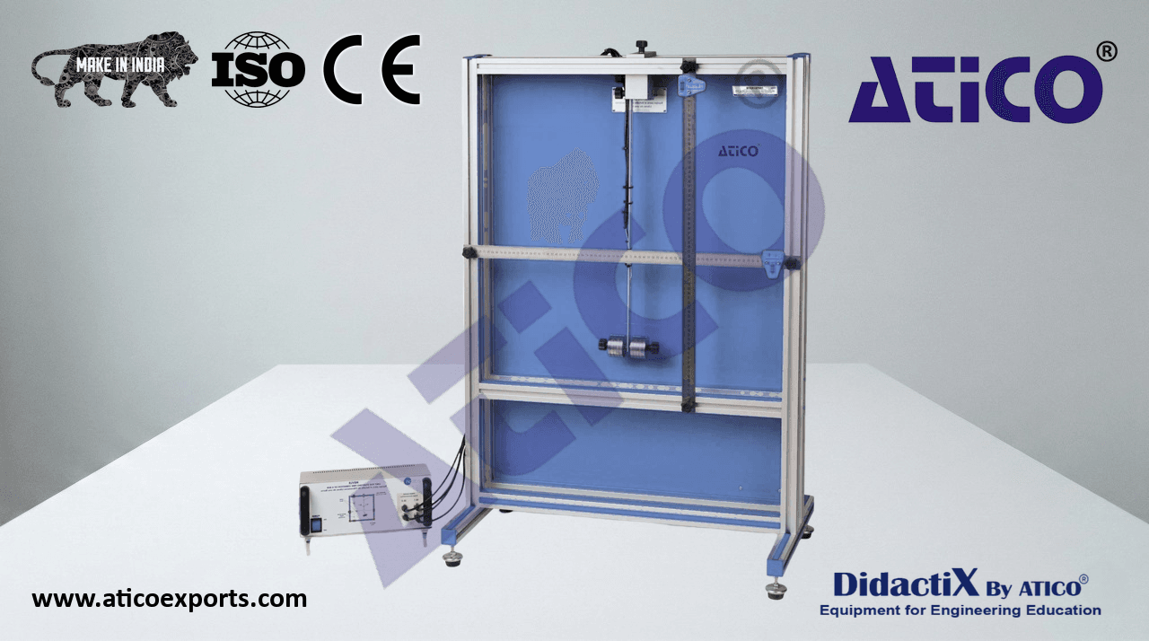
The main structure of the unit is a rigid frame, made of steel and aluminum, with two vertical guides, an upper mounting plate for the
spring, a lower mounting plate for the damper, a variable speed motor and a drive unit. This rigid frame supports the different elements
of the unit.
The mass carriage, to which various slotted weights may be attached, is constrained by
rollers which run along the vertical guides to provide a single degree of freedom with
minimum uncontrolled damping. The lower end of the spring is attached to the mass
carriage and the upper end is attached to the frame. This section of the frame is adjustable
so that the free position of the carriage may be varied.
The system uses two mechanical strip chart recorders that consists of a drum recorder and
- a pen holder:
The first records amplitude and frequency measurements. It has a drum recorder that
is attached to the rigid frame and consists of a drum, driven by a synchronous motor,
and a roll of paper. Before being rolled around the drum, the paper passes through
ATENG 12119 detail
a tensioning device that provides enough tension to ensure that the paper speed is
constant (0.02 m/s).
The second records amplitude and phase measurements. It also has a drum recorder that is attached to the rigid frame and consists of
a drum, wrapped in recording paper, driven by the main drive unit at the applied forcing angular frequency.
Both pen holders are attached to the mass carriage and use a spring to maintain continuous contact between the pen tip and the paper
on the drum.
- The variable speed motor and drive unit are attached to the rigid frame and provide two methods of forcing vibrations:
An unit consisting of two contra-rotating out-of-balance discs (mass = 0.742 Kg) may be attached to the mass carriage and are driven
by a flexible drive which is connected to the main drive unit. This provides a periodic disturbing force to the mass carriage.
A crank rotated by the drive unit and a connecting rod, which can be attached to the crank and the upper spring mounting, provides a
periodic displacement to the point of support of the spring.
Frequency of the oscillations can be measured with an optical sensor.
An electronic console is used to switch the synchronous motor on and off, control the speed of the forced vibrations motor and display the
frequency.
- Three springs, with varying stiffness, can be interchanged as the connection between the rigid frame and the mass carriage:
- Spring 1: k = 3.30 kN/m. Spring 2: k = 1.22 kN/m. Spring 3: k = 0.47 kN/m.
- Five weights of 1 kg each can be added and secured to the mass carriage.
An adjustable oil damper provides controlled damping and can be attached to the carriage by means of a screw.
Oil is provided to fill the damper.
Cables and accessories, for normal operation.