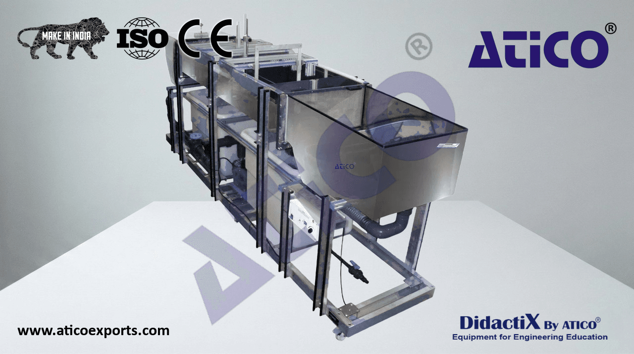
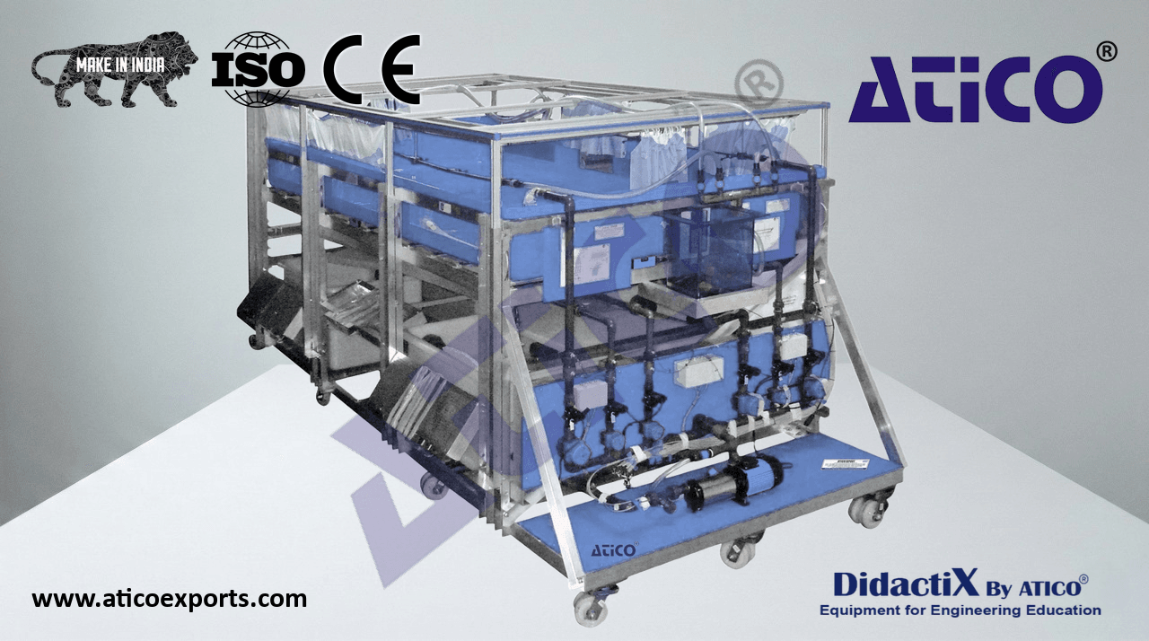
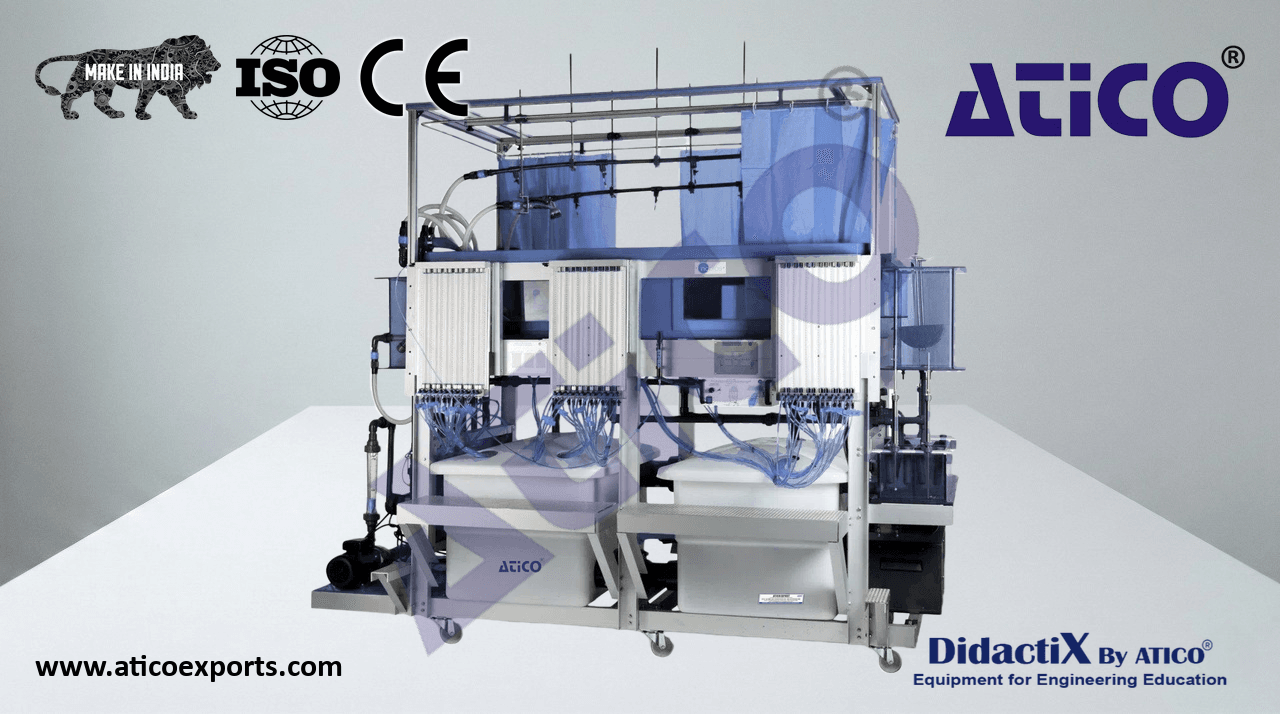
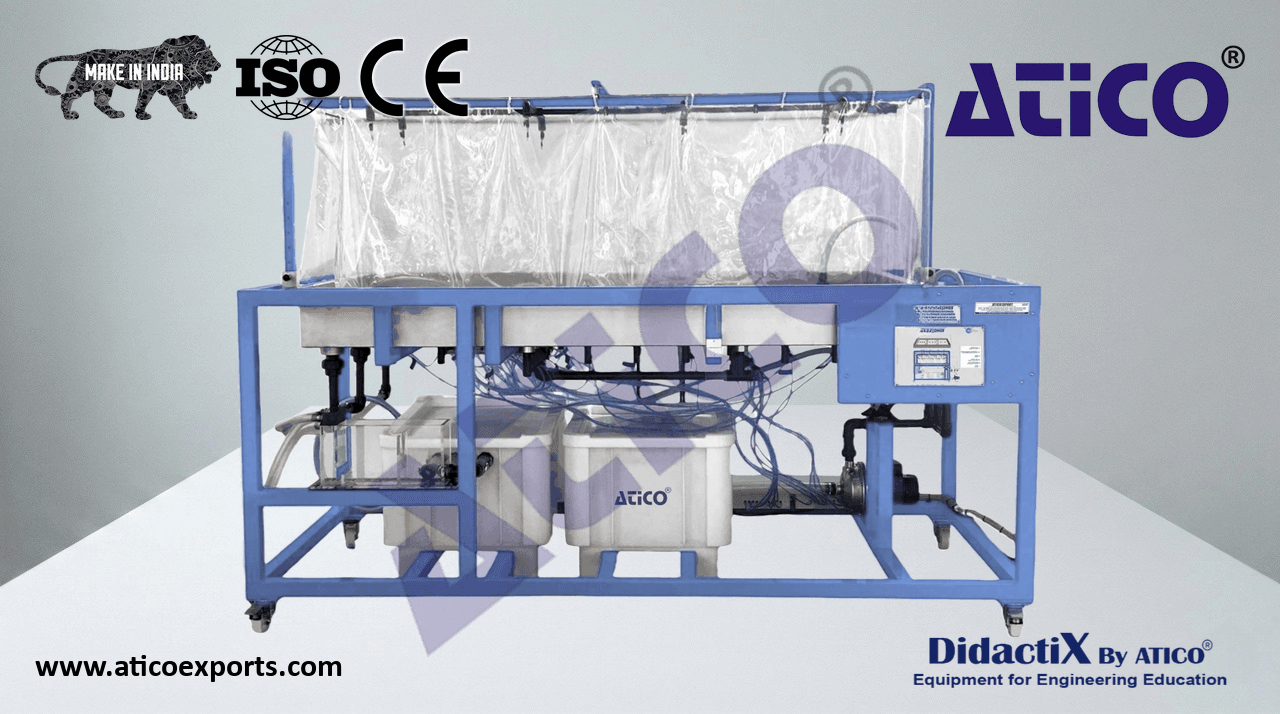
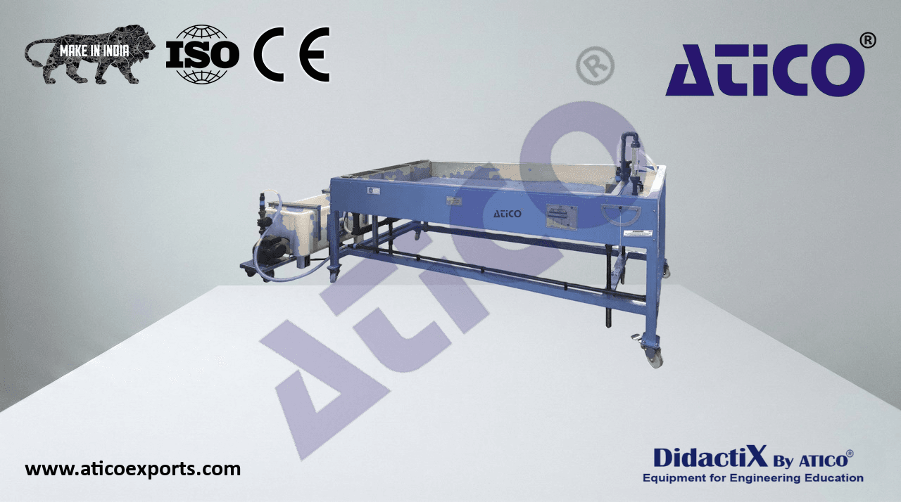
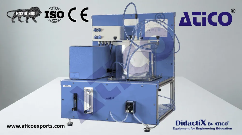
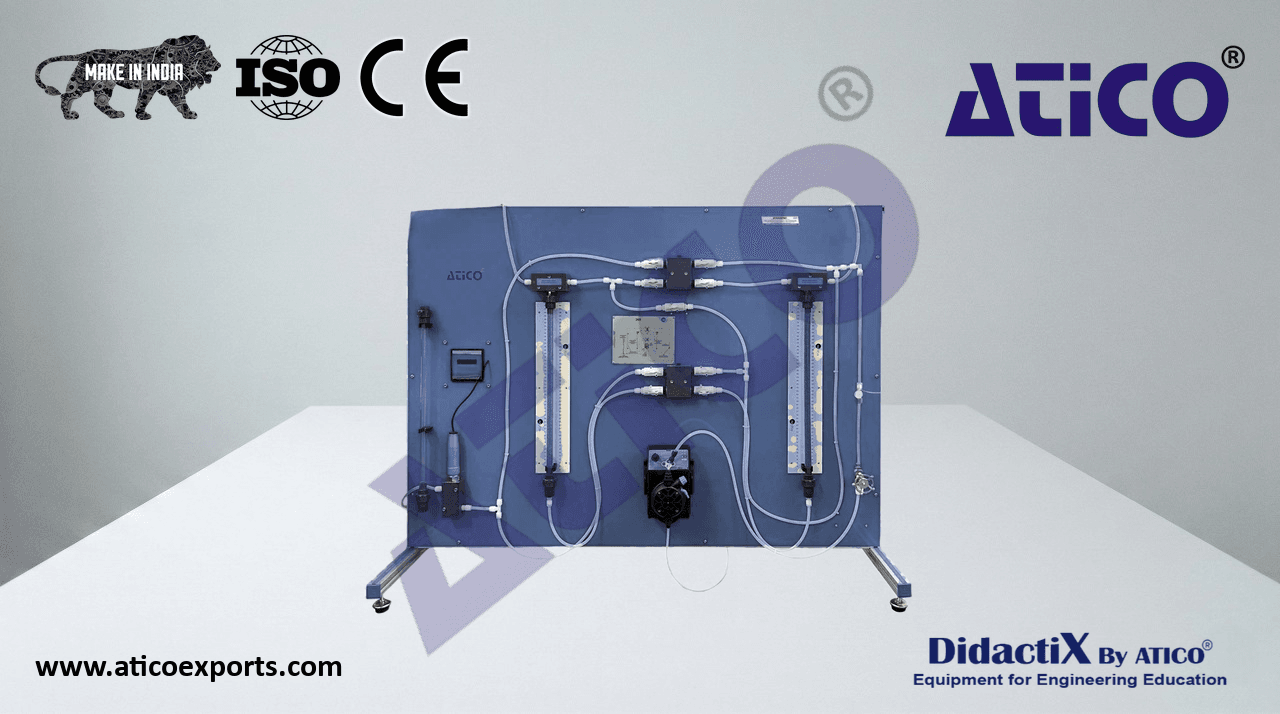
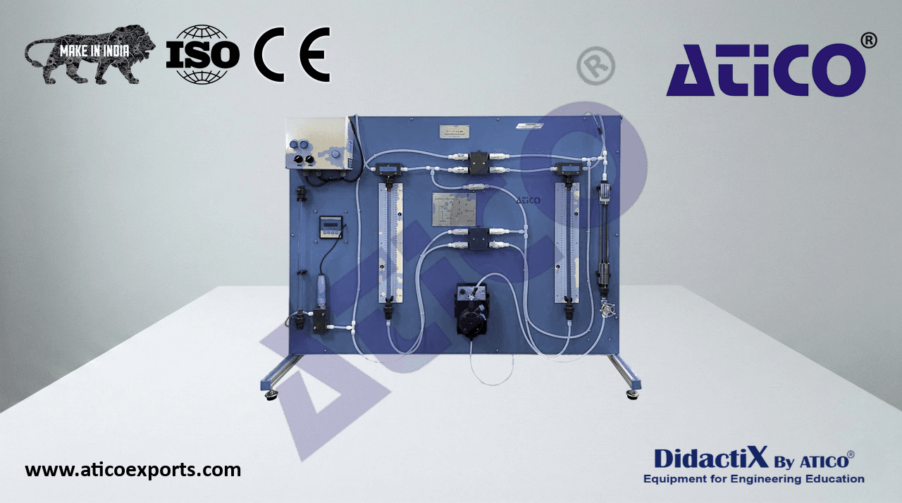
The Mobile Bed and Flow Visualization Unit (working section: 2000x610 mm)," ", is a particularly useful equipment to demonstrate the fluidization phenomenon in engineering.
Technical Specifications
ATENG 11806 — Mobile Bed and Flow Visualization Unit (working section: 2000X610 mm)
The Mobile Bed and Flow Visualization Unit (working section: 2000x610 mm), "ATENG 11806", is mounted on a metallic structure with wheels,
rigid and resistance enough to support the weight of water and sand without suffering any deformation.
All components in contact with water are of non-corrosive materials.
Diagram in the front panel with distribution of the elements similar to the real one.
This unit is divided into three sections: inlet tank, working section (channel) and discharge tank. These sections are assembled through
joints in order to get a complete assembly.
Stainless steel inlet tank, with adjustable hermetic overshot. It is supplied with
a control at the upper side of the tank which makes it possible to change the
slope of such overshot. The tank includes two perforated distributors and a
perforated plate to spread the flow evenly across the width of the tank. Inlet
tank dimensions: 530 mm x 710 mm x 530 mm.
Flow channel, made of stainless steel, including two main rails along the
working section with millimeter rulers (longitudinal crosspiece).
Instruments carrier which has a sub-rail (transverse crosspiece) is supported
on the rails and allow to put a gauge. Two sand traps can be coupled to both
ends of the working section. Dimensions: 2000 mm x 710 mm x 350 mm.
The working section is 2000 mm x 610 mm, and max. water depth is 120
mm approx.
Discharge tank, made of stainless steel, with overflow. It is divided into two
parts, the one closer to the channel enables the sedimentation of sand, using a
trap, whereas the second part enables the removal of the water which overflows
from the first part. Discharge tank dimensions: 850 mm x 710 mm x 530 mm.
Instrumentation:
Instruments carrier, which can be positioned over any point of the working
section.
Gauge designed to be mounted on the instruments carrier. It is provided
with a stainless steel hook and a point, and a Vernier scale.
Two water storage tanks, made of polyethylene, of approximately 250 l each one.
It has a filter at the pump inlet to retain possible residues, a butterfly valve and
an overflow that connects the storage tanks.
Centrifugal pump with flow regulation, range: 7.2 – 18 m³/h;
height: 14.4 –19.70 M.W.C.
Electromagnetic flow meter with display for the measurement and the reading
of the flow, range: 0.16 – 16.6 l/s.
Membrane valve.
Two different size gates to simulate an overflow and an obstacle in the working
section.
The traps of the working section, the discharge tank and the supply tanks are
movable elements than can be used to retain sand and solids
in the working section. They can also be removed to adjust the channel to
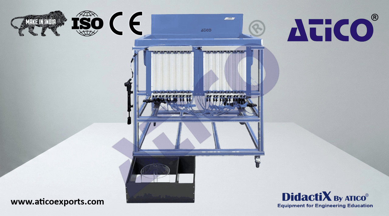
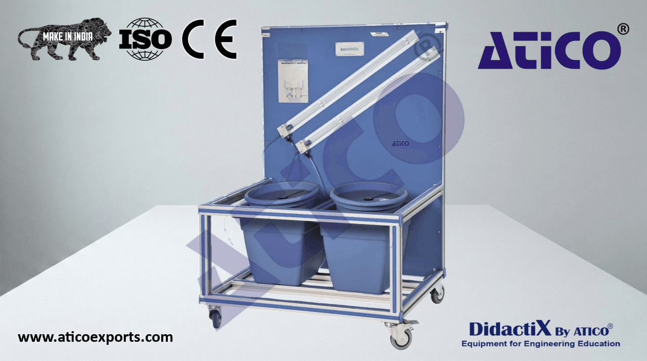
different working conditions. ATENG 11806 detail
Set of models included:
Bridge piers models:
Two rectangular models.
Four cylindrical models.
Four square models.
Two profiled rectangular models.
Two rectangular models with rounded ends.
Triangular model.
Asymmetrical aerofoil model.
Six baffles to direct the water flow during the experimental tests.
Set of 12 “L” shaped profiles.
Three pairs of different angles to build additional models.
The practical exercises with this unit are carried out by using water and sand.
Electronic console:
Centrifugal pump on/off switch.
Flow controller for the centrifugal pump. ATENG 11806 details
Principal switch.
Cables and accessories, for normal operation.