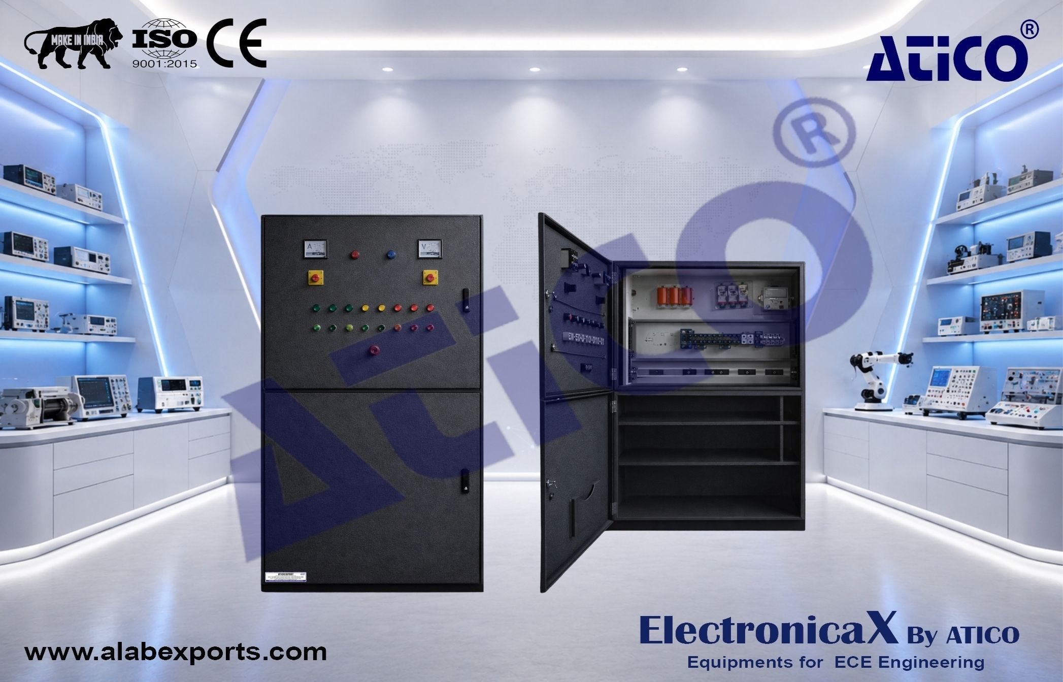
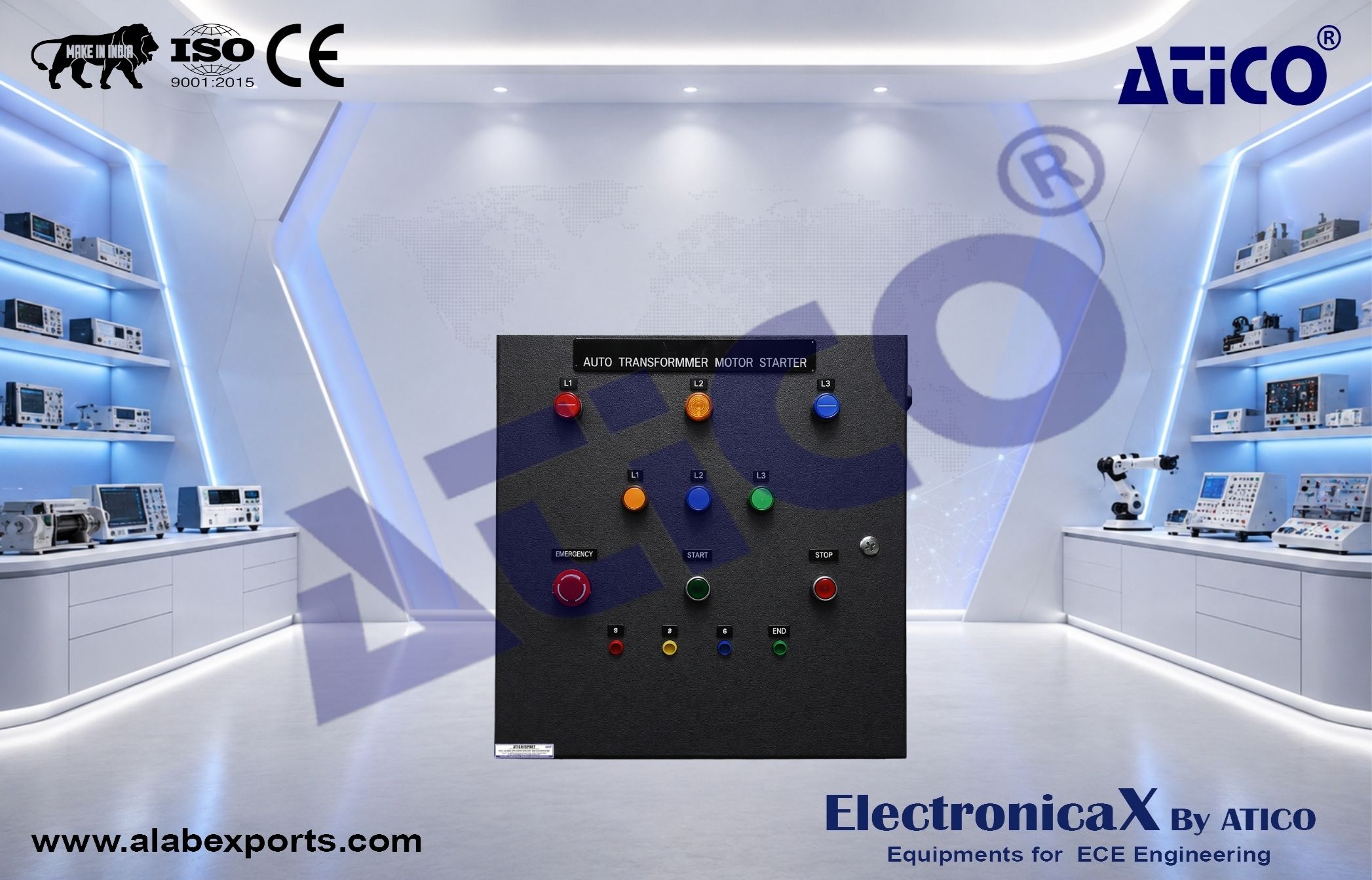
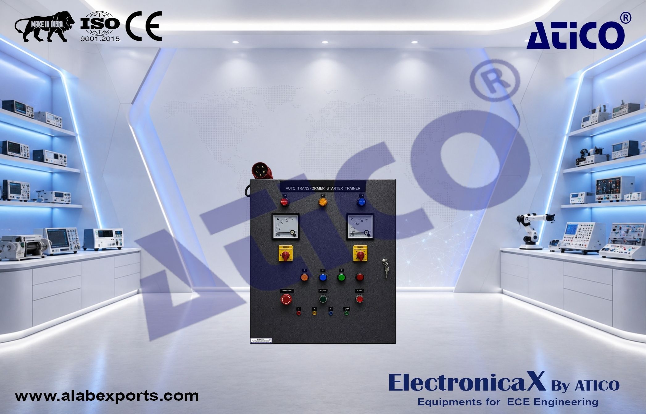
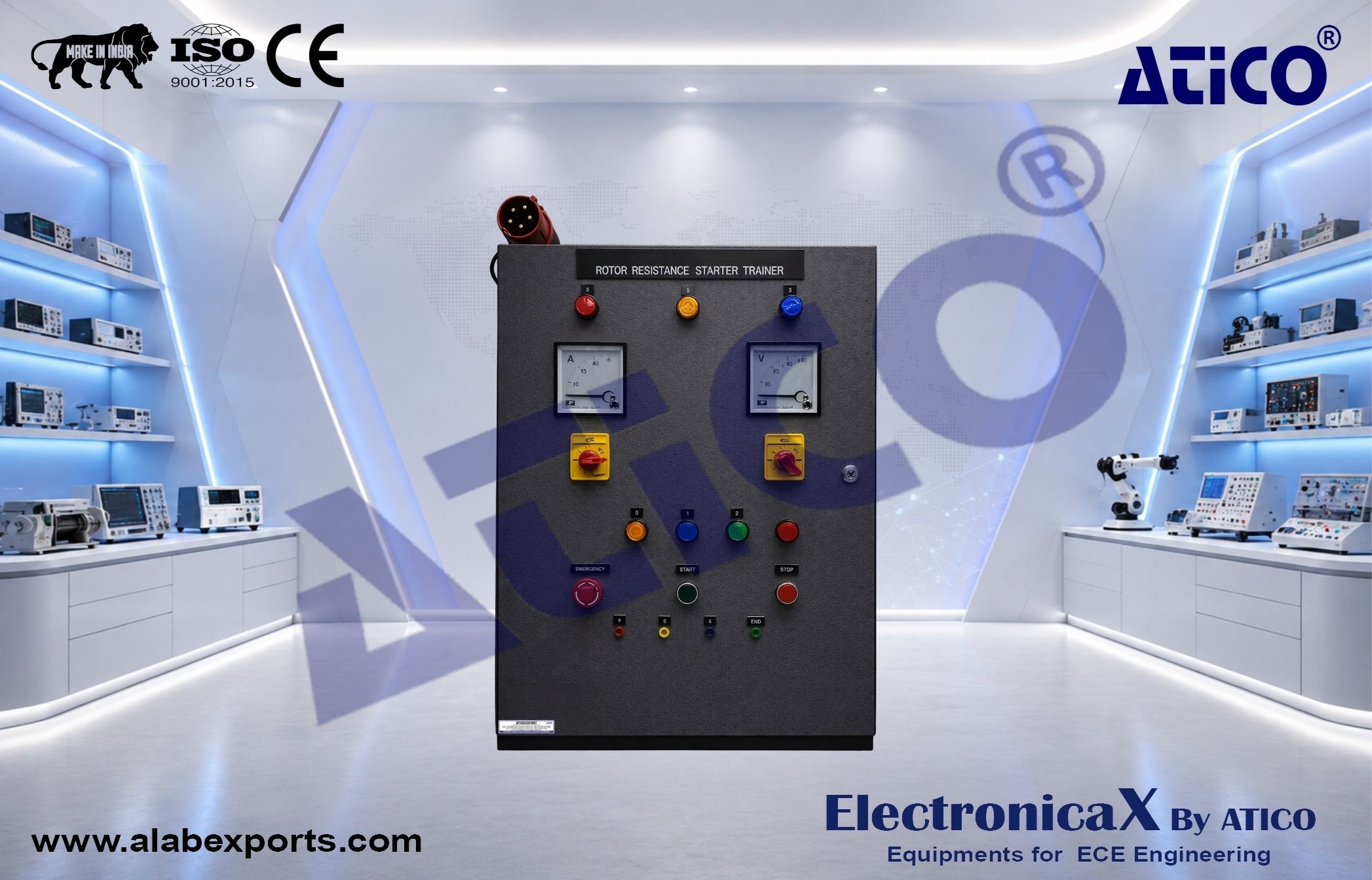
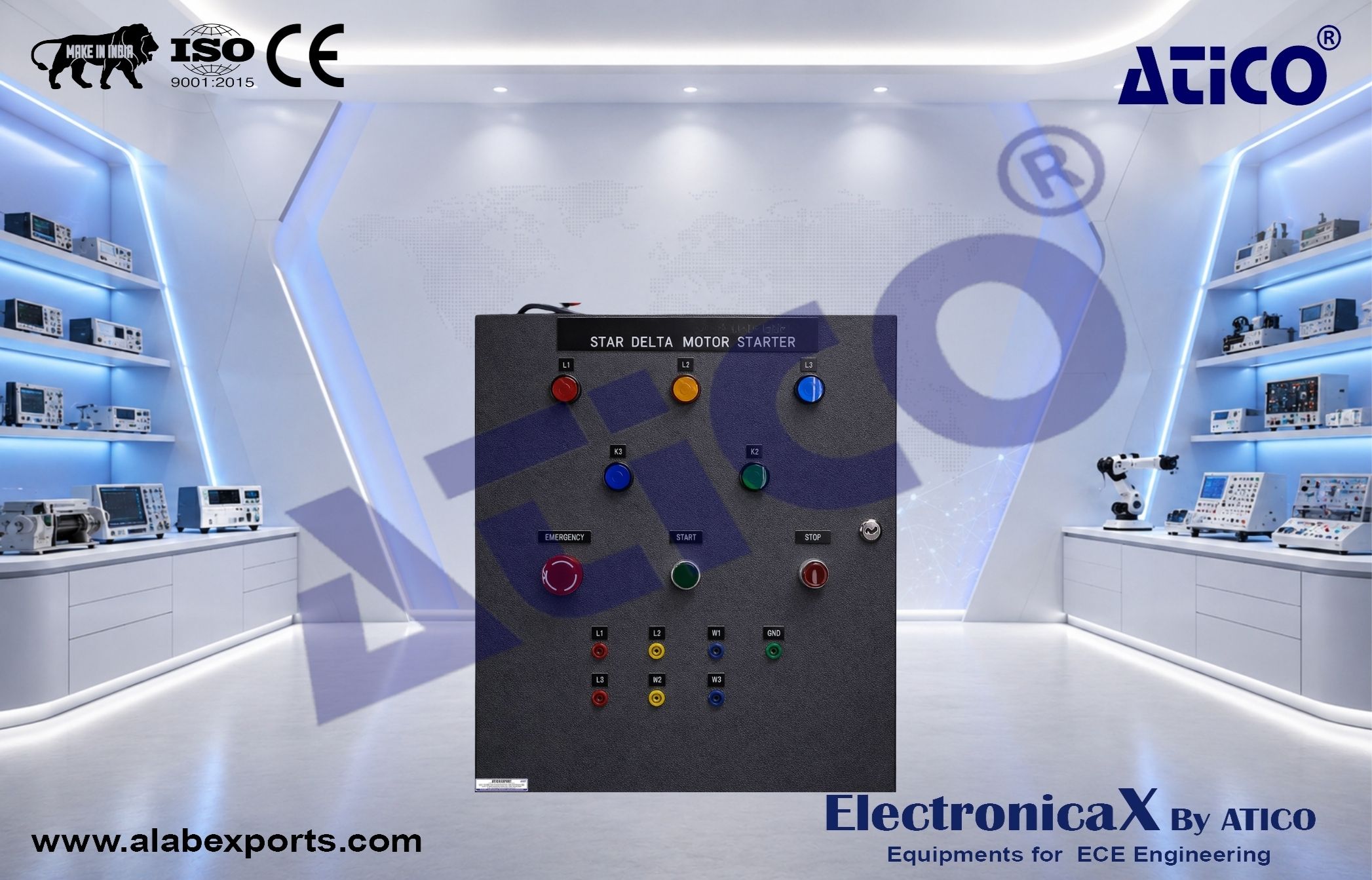
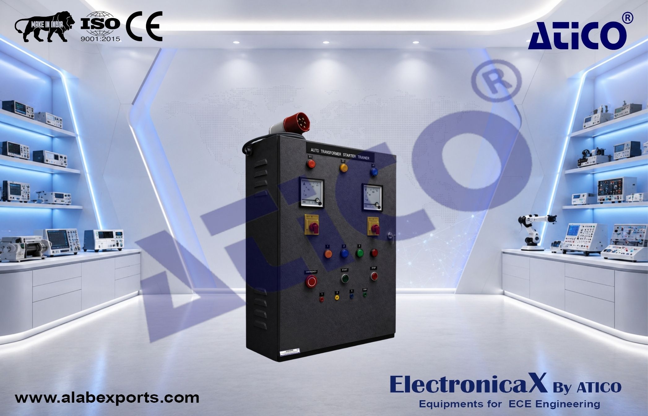
- 1.1 This motor control panel are designed to start, operate and control the electrical motor
- 1.2 All of the standard controls, protections and instruments are containing IEC standards and safety (include cable connection to terminal)
- 1.3 All equipment/components must be mounted on panel box and without wire (for student self-wiring practice)
- 1.4 All front panel compartments/parts are clearly labeled marked to ensure easy reference and better understanding of the internal circuitry and/or components functions
- 1.5 All terminal connections and terminations are clearly numbered, marked and labeled
- 1.6 Marking: Engraved legends
- 1.7 Mounting: Equipment is mobile with heavy duty locking swivel castor wheel
- 1.8 Panel Box: Heavy sheet steel metal console finished by baked epoxy powder coating
- 1.9 Provision for external connection via safety type terminal socket on terminal box
- 1.10 Approx. size: 600 (L) x 400 (W) x 1500 (H) mm
Suruhanjaya Tenaga Syllabus Chargeman Category A0
Module: Motor and its starter
- a) Types of motor, usage, difference and movement
- b) Maintenance, damage detection and repair
- c) Starter including characteristics of protection
2.0 TECHNICAL SPECIFICATION
2.1 Front Panel complete with accessories specification:
- 2.1.1 1 unit Analogue AC Ammeter: 0 – 40 A
- 2.1.2 1 unit Analogue AC Voltmeter: 0 – 500 Vac
- 2.1.3 1 unit Selector Switch for Auto-Off-Manual
- 2.1.4 1 unit Ammeter Selector Switch
- 2.1.5 1 unit Voltmeter Selector Switch
- 2.1.6 2 units Selector Switch On-Off for Trip function
- 2.1.7 1 unit Mushroom Head Emergency Stop Button
- 2.1.8 2 unit Green Push Button Switch (2 x Start)
- 2.1.9 2 units Red Push Button (2 x Stop)
- 2.1.10 1 unit Green Push Button (1 x Forward)
- 2.1.11 1 unit Green Push Button (1 x Reverse)
- 2.1.12 3 units LED Pilot Lamp (Red/Yellow/Blue) – Main Phase Lamp
- 2.1.13 5 units Red LED Pilot Lamp (2 x Stop, 2 x Trip and 1 x Emergency Switch)
- 2.1.14 2 units Green LED Pilot Lamp (2 x Run)
- 2.1.15 1 unit Blue LED Pilot Lamp (1 x Forward)
- 2.1.16 1 unit White LED Pilot Lamp (1 x Reverse)
- 2.1.17 2 units Amber LED Pilot Lamp (1 x Auto and 1 x Manual)
2.2 Internal panel complete with accessories specification:
- 2.2.1 1 unit Molded Case Circuit Breaker 60 A 3 Pole
- 2.2.2 3 units Miniature Circuit Breaker 32 A 3 Pole
- 2.2.3 1 unit Miniature Circuit Breaker 6 A 2 Pole
- 2.2.4 3 units Miniature Circuit Breaker 6 A 1 Pole
- 2.2.5 5 units Magnetic Contactor 2 NO 2 NC 30 A 230 Vac
- 2.2.6 3 units Time Delay Relay 8 pin 2 NO 2 NC (all function)(0 – 60 s) c/w base
- 2.2.7 3 units Thermal Overload Relay 4 terminal (12 – 18 A)
- 2.2.8 3 units Relay 230Vac 14 terminal c/w base
- 2.2.9 1 unit Auto Transformer 7.5 kW 3 Phase (wired to terminal block 10 way, 600Vmax, 30A)
- 2.2.10 1 unit Rotor Resistance 7.5 kW (wired to terminal block 10 way, 600Vmax, 30A)
- 2.2.11 1 unit Soft Starter 7.5 kW/ 600V
- 2.2.12 3 units Current Transformer 30/5 A, 5VA CL3 c/w bracket
- 2.2.13 Terminal Block with marker: 60 ways, 600 V max, 10A
- 2.2.14 DIN Rail
2.3 Side panel complete with accessories specification:
- 2.3.1 6 units ventilation fan 100 mm x 100 mm (3 x left side and 3 x right side)
- 2.3.2 Incoming Industrial Socket Outlet: 32 A TPN industrial female socket