1.0 Basic Principle Of AC Motor
- Types of AC motor, structure of asynchronous motor and basic of AC motor.
2.0 Electric Driver
- Characteristics of motor operating at various torque and speed-electric driver, torque-speed curve, current speed curve
3.0 Voltage Control And Inverters
- Explanation on voltage control in inverters – pulse-width control (PWC) and pulse-width modulation (PWM)
4.0 Speed Control By Variable Stator Voltage
- Method of controlling squirrel cage motor speed by variable stator voltage
5.0 Current-Fed And Voltage-Fed Inverters
- Speed control of squirrel cage motor by variable frequency – function of self-commutated inverter, voltage-fed and current-fed terminology, operation of current-fed and voltage-fed inverters substation, distribution substation
6.0 Other Types Of Control
- Types of motor speed control – cycloconverter control by using power electronic experiments modules.
SYLLABUS
1.0 INTRODUCTION TO AC MOTOR
- 1.1 Understand types of AC motor
- 1.1.1 Describe synchronous motor
- 1.1.2 Describe asynchronous motor – squirrel cage rotor
- 1.1.2 Describe asynchronous motor – wound (slip ring) rotor
- 1.1.3 Describe universal motor
1.2 Study the structure of asynchronous motor
- 1.2.1 Describe rotor and types of rotor in induction motor
- 1.2.2 Explain connection of the rotor in induction motor
- 1.2.3 Compare between squirrel cage rotor and wound (slip ring) rotor
- 1.2.4 Describe stator
- 1.2.5 Explain connection of the stator in star and delta connection
1.3 Understand the basic of AC motor
- 1.3.1 Define synchronous speed, slip and slip frequency
- 1.3.2 Determine synchronous speed (Ns)
1.4 Study the transfer of power in an AC motor
- 1.4.1 Draw diagram of the power transmission of an induction motor
- 1.4.2 Explain the power of the transmission of an induction motor
- 1.4.3 Construct equivalent circuit of an induction motor using calculation and related formula
1.5 Know the methods of AC motor control
- 1.5.1 Compare the characteristics of AC motor control by varying
- a. Voltage
- b. Frequency
- c. Number of poles
- d. Rotor–s resistance
2.0 ELECTRIC DRIVER
- 2.1 Study the electrical driver in AC motor
- 2.1.1 Define an electrical driver
2.1.2 Compare types of AC drivers
a. Static Frequency Changers
b. Static Voltage Controllers
c. Rectifier-inverter System with Line Commutation
d. Rectifier-inverter System with Self Commutation
e. Pulse Width Modulation Systems
2.2 Understand torque-speed curve
- 2.2.1 Construct the torque-speed curve for induction motor
- 2.3 Understand current-speed curve
- 2.3.1 Sketch the shape of current versus speed curve for induction motor
- 2.3.2 State the effects on the current-speed curve when stator voltage and frequency are varied at the same rate
- 2.3.3 Solve the related problems using calculation or graphical plotting
3.0 VOLTAGE CONTROL IN INVERTERS
3.1 Understand Pulse Width Control – USING TWO / SIX PULSE CONTROLLER
- 3.1.1 Explain the meaning of Pulse Width Control
- 3.1.2 Draw a single phase bridge inverter circuit and the suitable waveforms
- 3.1.3 Sketch output waveforms
- 3.1.4 Sketch the waveform for Triggering gate control for thyristors and transistors
- 3.1.5 Explain the circuit operation
3.2 Understand Pulse Width Modulation – Using PWM CONTROLLER
-
3.2.1 Explain the meaning of Pulse Width Modulation
-
3.2.2 Explain the formation of a PWM using sawtooth and sinusiodul wave technique
-
3.2.3 Draw the Pulse Width Modulation waveforms for an inverter using sawtooth and sinusiodal waveform
a. maximum output voltage, high frequency
b. half of the maximum output voltage, high frequency
c. half of the maximum output voltage, half of high frequency
- 3.2.4 Determine the current and voltage waveform of a simple Pulse Width Modulation through calculation using related formulas
3.3 Study the single phase bridge inverter circuit
- 3.3.1 Analyze the output voltage and current of inverter circuit without PWM
- 3.3.2 Determine the related parameters to plot graph
- 3.3.3 Analyze the output voltage and current of inverter circuit with PWM
4.0 SPEED CONTROL BY VARIABLE STATOR VOLTAGE
4.1 Study the three phase squirrel cage induction motor control method by variable stator voltage
- 4.1.1 Draw voltage control circuit by means of thyristors
- 4.1.2 Sketch characteristics curve of torque control versus speed at varies voltage values
- 4.1.3 Explain thyristors triggering sequence to control voltage
- 4.1.4 Draw current and phase voltage waveforms at rated voltage
- 4.1.5 Explain thyristors switching sequence to control forward and reverse
5.0 CURRENT-FED AND VOLTAGE-FED INVERTERS
5.1 Understand speed control of the squirrel cage motor using variable frequency inverter
- 5.1.1 Write the function of self-commutated inverter in squirrel cage induction motor
- 5.1.2 Describe basic principles of self-commutated inverter with using a circuit diagram
- 5.1.3 Explain operation of rectifier-inverter system for squirrel cage induction motor speed control
- 5.1.4 Explain concepts of voltage-fed and current-fed
- 5.1.5 Define voltage-fed inverter
- 5.1.6 Give a simple example to justify the change in voltage does not happen in a fast pace
- 5.1.7 Define current-fed inverter
- 5.1.8 Give a simple example to justify the change in current does not happen in a fast pace
5.2 Understand operation of current-fed inverter driver (fixed current)
- 5.2.1 Draw current-fed inverter driver system circuit
- 5.2.2 Explain operation of the circuit
- 5.2.3 Draw waveform of the motor when it is fed from a fixed current inverter
- 5.2.4 Give two advantages of inverter
- 5.2.5 Explain how regenerating braking can be obtained
5.3 Understand the operation of voltage-fed inverter driver (fixed voltage)
- 5.3.1 Draw a labeled voltage-fed inverter driver system circuit
- 5.3.2 Compare operation of the circuits
a. 120 degrees triggering
b. 180 degrees triggering
- 5.3.3 Draw waveform of motor line voltage and current
6.0 OTHER TYPES OF CONTROL
6.1 Study other types of motor speed control
- 6.1.1 Construct a circuit diagram and waveforms to explain cycloconverter control
- 6.1.2 Construct a circuit diagram and waveforms to explain operation of the squirrel cage induction motor uses cycloconverter control
6.2 Understand methods of starting a motor
- 6.3.1 Explain briefly method of starting a motor
- 6.3.2 Explain Soft Starting of an induction motor
6.3 Understand methods of slowing down a motor
- 6.4.1 Apply a circuit diagram to explain a method of slowing down an induction motor by injection direct current
- 6.4.2 Explain the methods of controlling a motor
a. Plugging b. Jogging / Inching
c. Regenerating braking
EXPERIMENTS MODULE – ELECTRICAL MACHINE
THREE PHASE INDUCTION MOTOR
THREE PHASE SLIP RING MACHINE
- Nominal Power: 370W (1/2HP)
- Nominal Voltage: 450 / 690V (Delta/Star)
- Nominal Current: 2.50 / 1.50A (Delta/Star)
- Nominal Speed: 3000 rpm
- Cooling Method: Total Enclosed Fan Control
- Terminals: 4mm Safety Socket
- Base Plate: Attachable To Break Load Unit
- Coupling: EM-21-CS (Option)
- Nominal Power: 370W (1/2HP)
- Nominal Voltage: 240 / 415V (Delta/Star)
- Nominal Current: 4.5 / 4.0A (Delta/Star)
- Nominal Speed: 1500 rpm.
- Frequency: 50Hz
- Cooling Method: Self Cooling
- Terminals: 4mm Safety Socket
- Base Plate: Attachable To Break Load Unit
THREE PHASE SYNCHRONOUS MACHINE
- Nominal Power: 350W (1/2HP)
- Nominal Voltage: 240 / 415 V (Delta/Star)
- Nominal Current: 1.85 / 2.85 A (Delta/Star)
- Nominal Speed: 1500 rpm
- Frequency: 50 Hz
- Excitation Voltage: 0 ~ 25VDC
- Excitation Current: 2.50 A
- Cooling Method: Self Cooling
- Terminals: 4mm Safety Socket
- Base Plate: Attachable To Break Load Unit
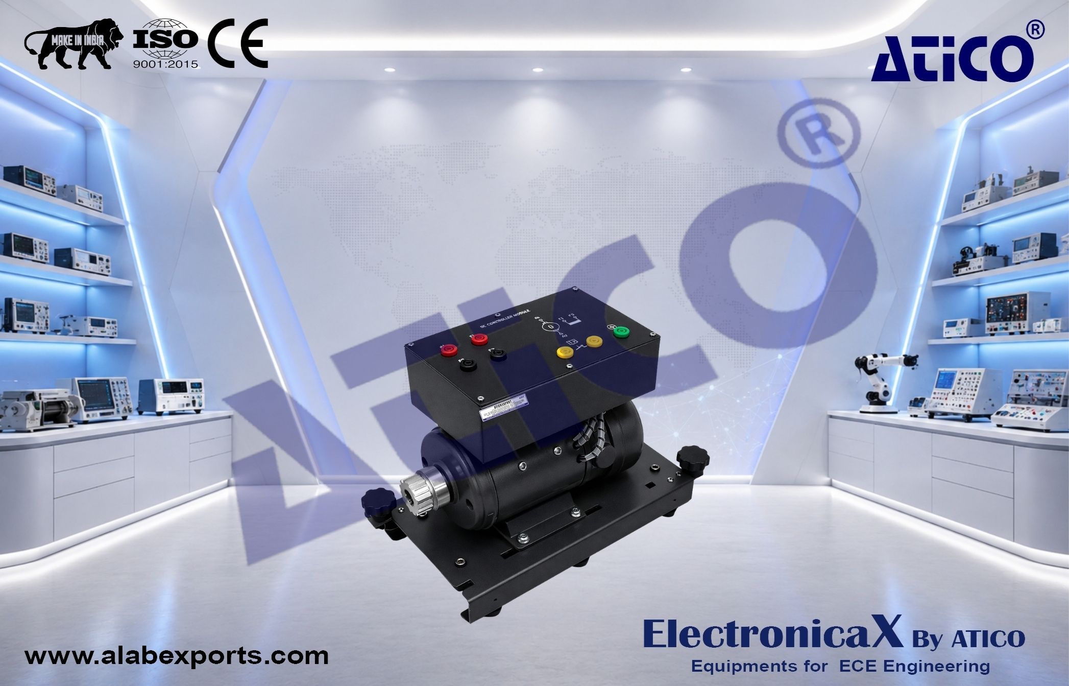
- Nominal Power: 370W (1/2HP)
- Nominal Voltage: 220VDC
- Nominal Current: 1.50
- Nominal Speed: 1500 rpm
- Terminals: 4mm Safety Socket
- Base Plate: Attachable To Break Load Unit
THREE PHASE INDUCTION MOTOR
- Nominal Power: 750W (1HP)
- Nominal Voltage: 240 / 415V (Delta/Star)
- Nominal Current: 2.85 / 1.85A (Delta/Star)
- Nominal Speed: 1500 rpm
- Cooling Method: Total Enclosed Fan Control
- Terminals: 4mm Safety Socket
- Base Plate: Attachable To Break Load Unit
- Nominal Power: 750W (1HP)
- Nominal Voltage: 240V/415AC
- Nominal Current: 2.5A
- Nominal Speed: 1500 rpm.
- Frequency: 50 Hz
- Excitation: Permanent Magnet
- Cooling Method: Self Cooling
- Terminals: 4mm Safety Socket
- Base Plate: Attachable To Motor Unit
SINGLE PHASE CAPACITOR START MOTOR
- Nominal Power: 370W (1/2HP)
- Nominal Voltage: 240VAC
- Nominal Current: 2.5A
- Nominal Speed: 1500rpm
- Frequency: 50Hz
- Power Factor: 0.78
- Winding Poles: 4
- Terminals: 4mm Safety Socket
- Base Plate: Attachable To Break Load Unit
- Nominal Power: 370W (1/2HP)
- Nominal Voltage: 240VAC
- Nominal Current: 2.5A
- Nominal Speed: 1500rpm
- Frequency: 50Hz
- Power Factor: 0.78
- Winding Poles: 4
- Terminals: 4mm Safety Socket
- Base Plate: Attachable To Break Load Unit
TORQUE SENSOR MODULE
- Motor direct coupling design
- Sensor Type: Noncontact rotation torque transducer
- Max. torque: °10Nm
- Max Rotation speed: 12000rpm
- Torque Output: Frequency
- Speed Output: Frequency
- Connection: Coupling with Motor & Generator
- Real Time Data Logging: Data is automatically logged when data is updated.
- Data collection the measured data by computer serial port
- Display and save the real-time data
- Transform the saved data to TXT, EXCEL file
- By curve analyses, curve print, trend browse, report generation, report edition and report print, etc.
TORQUE SPEED MEASURING MODULE
Modular design
- Unit Type: Panel H2
- Torque range: -99999-99999 N.m, Torque display: 0-99999N.m, decimal position adjustable.
- Speed display: 0-99999, decimal position adjustable
- Power consumption: 0-99999, decimal position adjustable
- Measurement resolution: support resolution 1/1000000
- Measuring speed: 25 times per second
- Pulse input signal: all kinds of output sensor signal, like NPN, PNP, OC, switches and rotary encoder
Measurement Frequency:
- Speed pulse input 0.3Hz–20KHz
- Torque pulse input, 5KHz–15KHz, can extend to 1HZ~60KHZ
- Standard transmitter output
- Optoelectronic isolation
- Two 4mA~20mA DC current output, Output resolution ratio: 1/4000–error less than °0.2%, F.S, loading capacity: less than 600°
- External Power Supply: °15VDC, loading capacity more than 300mA
- Serial communication port as standard configuration
- Optoelectronic isolation
DIGITAL DC VOLTMETER
Modular design
- Measurement range : DC 0 ~ 600V
- Display : 3 ° digits 14.2 mm LED
- Accuracy : ° 0.2% ° 1 digit
- Resolution : 1V
- Input impedance : 1M°
- Power source : 220Vac, 50/60 Hz
- Unit Type : Panel H1
- Terminals: 4mm Safety Sockets
Modular design
- Measurement range : DC 0 ~ 10A
- Display : 3 ° digits 14.2 mm LED
- Accuracy : ° 0.3% ° 1 digit
- Resolution : 0.01 A
- Input impedance : < 0.1°
- Power source : 220Vac, 50/60 Hz
- Unit Type : Panel H1
- Terminals: 4mm Safety Sockets
DIGITAL AC VOLTMETER
- Modular design
- Measurement range : AC 0 ~ 600V
- Display : 3 ° digits 14.2 mm LED
- Accuracy : ° 0.2% ° 1 digit
- Resolution : 1V
- Input impedance : 1M°
- Power source : 220Vac, 50/60 Hz
- Unit Type : Panel H1
- Terminals: 4mm Safety Sockets
- Modular design
- Measurement range : AC 0 ~ 5A
- Display : 3 ° digits 14.2 mm LED
- Accuracy : ° 0.3% ° 1 digit
- Resolution : 0.01 A
- Input impedance : < 0.1°
- Power source : 220Vac, 50/60 Hz
- Unit Type : Panel H1
- Terminals: 4mm Safety Sockets
SINGLE PHASE POWER ANALYSIS METER
- Modular design
- Display Type: Digital LED Display
- Measuring Function:
- Voltage V,
- Current A, – Active Power KWH,
- Reactive Power VAR,
- Appearant Power VA,
- Power Factor PF,
Measuring Range :
- Voltage : 6 ~ 600V
- Current : 0.015 ~ 5A
- Analog Output: 4 ~ 20mA (Optional)
- Alarm Output: Two Alarm Free Setting NC, NO (Optional)
- Communication : RS485, MODBUS RTU Protocol (Optional)
- Accuracy: °0.5%
- Protection: Fuse
- Power Supply: 85 ~ 265VAC, 50Hz
- Terminals: 4mm Safety Socket
- Unit Type : Panel H1
THREE PHASE POWER QUALITY METER C/W SCADA/RTU
- Modular design
- Display Type: HD LCD Display
- Real-Time Measurement
- Phase voltage: V1, V2, V3, Vlnavg Line voltage: V12, V23, V31, Vllavg Current: I1, I2, I3, Iavg, In Active power: per phase and total active power Reactive power: per phase and total reactive power Apparent power: per phase and total apparent power Power factor: per phase and total power factor Total frequency
- Energy And Demand
- Four quadrant active energy: Import, Export, Total, Net Four quadrant reactive energy: Import, Export, Total, Net Active, Reactive, Apparent demand
- Power Quality Analysis
- Voltage unbalance Current unbalance Voltage THD (Total harmonic distortion), Odd-even harmonic distortion Voltage individual harmonics, Crest factor Current THD, Odd-even harmonic distortion Current individual harmonics, K factor
Communication (SCADA/RTU)
- Ethernet 10/100M network port
- RS485 communication port
- MODBUS RTU communication protocol
Trend Logging
- Phase voltage Line voltage Current Active power Reactive power Apparent power Power factor Frequency Three-phase unbalance Active energy Reactive energy Apparent energy Phase
Settable Logging Interval
- Logging from 1min to 60min, interval settable
Software Accessibility
- 4 Tariffs (DataLog) Sharp, peak, flat, valley in different season and schedule (TOU)
- PowerMeter Management Software Interface
- Accuracy: °0.5%
- Protection: Fuse
- Power Supply: AC240VAC, 50Hz
- Terminals: 4mm Safety Socket
POWER MANAGEMENT SOFTWARE
- PC management software; web browse data
- True-RMS measuring parameters
- ANSI and IEC 0.2 accuracy class
- Power quality analysis
- 4 quadrant energy
- Data logging
- Measure individual harmonics from 2nd to 49th
- TOU, 4 Tariffs, 6 Seasons, 6 Schedules
Single & Three phase Resistive Load 7 steps variable per phase
- Max Power : 3°100 watt
- Voltage : 240/415VAC
- Frequency : 50Hz
- Protection : Fuse
STAR DELTA STARTING SWITCH MODULE
- Modular design
- Switch load: 400VAC/15A
- Switch positions: 0-1-2 (0-Y-–)
- Unit Type : Panel H1
- Terminals : 4 mm safety sockets (Color Coded)
- Modular Design
- Switch Load: 400VAC/15A
- Switch positions: FORWARD-OFF-REVERSE
- Unit Type : Panel H1
- Terminals: 4mm Safety Sockets (Color Coded)
UNIVERSAL AC & DC POWER SUPPLY
The system designed to provide all fixed and variable AC and DC supplies which necessary in an electrical machines laboratory to perform the experiment required and work project.
The unit is contained in a metal housing with clear front panel label and 4mm safety sockets that make its easy and safety for student experiments.
Specification
- Power Input Requirement: Three Phase 240V/415V, 50Hz
- Connection: 3P+N+PE Output terminations by using 4mm terminals socket.
- Input fed with AC 5 pin plug 32A AC Plug and Socket.
- Pilot lamps are provided to indicate all live supplies.
- With On/Off Selector Switch
- Fuse Protection
- Power Rating: 3KVA
- Output Supply Section
Fixed Single Phase AC Power Supply:
- 3 x 240V AC; 5A AC (Phase To Neutral; R-N, B-N, Y-N)
Fixed Three Phase AC Power Supply:
- 3 x 450V AC; 5A AC (Phase To Phase; R-Y, Y-B, B-R)
Adjustable Single Phase & Three Phase AC / DC Power Supply (Simultaneously):
- 3 x 0 ~ 450VAC; 5A AC (Phase To Phase)
- 3 x 0 ~ 240VAC; 5A AC (Phase To Neutral)
- 1 x 0 ~ 430VDC; 5A DC (DC Output)
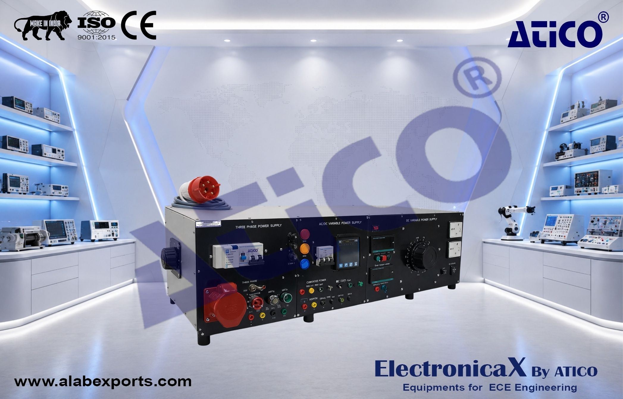
UNIVERSAL AC/DC POWER SUPPLY
The system designed to provide all fixed and variable AC and DC supplies which necessary in an electrical machines laboratory to perform the experiment required and work project.
The unit is contained in a metal housing with clear front panel identification and 4mm safety sockets that make its easy and safe.
Three Phase Power Supply
- Power Input: 3 Phase 240V/415V, 50Hz via input 5 core cable with 5 pin AC Plug, 32A
- 5 Pin AC Socket Output 16A
- Indicator: 3 pilot lamp for power line in three color coded. (Red, Yellow & Blue)
- Fuse Protection: Three Phase Output
- Connection: 3P+N+PE.
- Emergency Push Button Switch
- Keylock Switch
- START Push Button Switch
- STOP Push Button Switch
- Protection: Earth leakage circuit breaker and miniature circuit breaker and AC Contactor
- Fixed Three Phase AC Power supply: 3 x 415V AC; 32A AC (Line To Line)
- Fixed Single Phase AC Power supply: 3 x 240V AC; 32A AC (Line To Neutral)
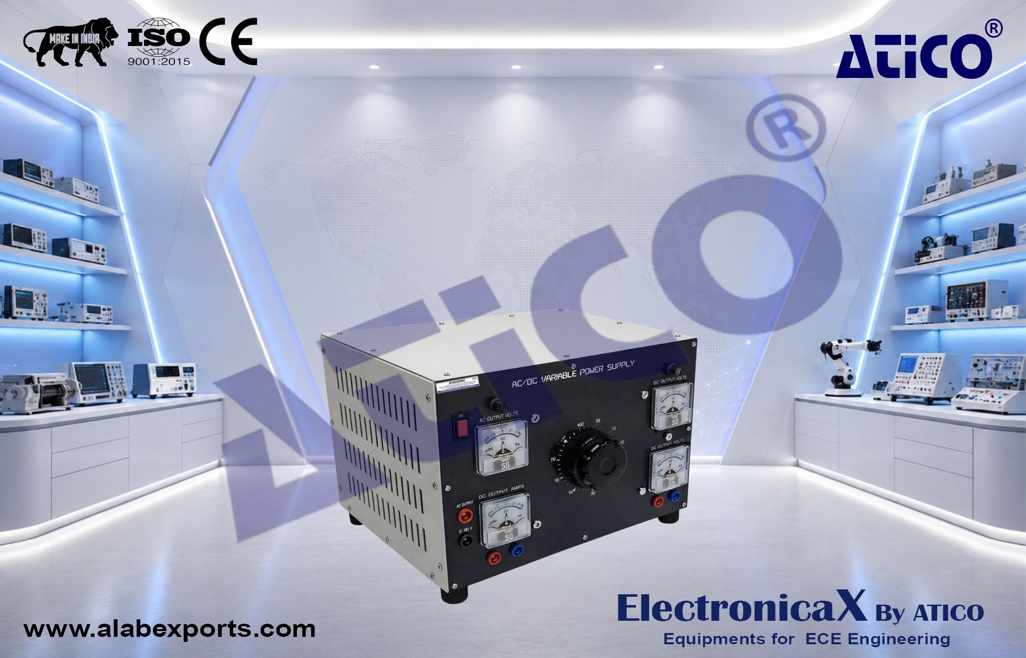
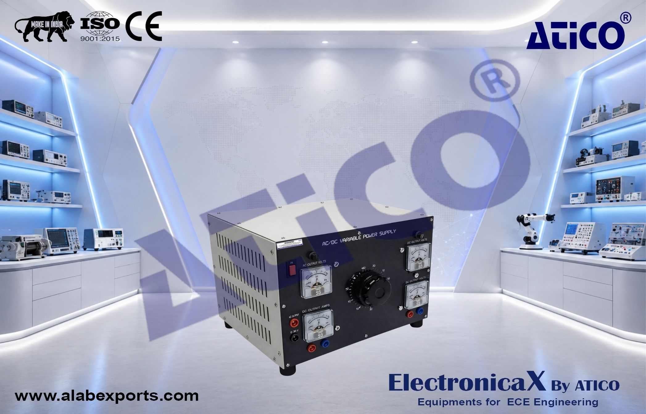
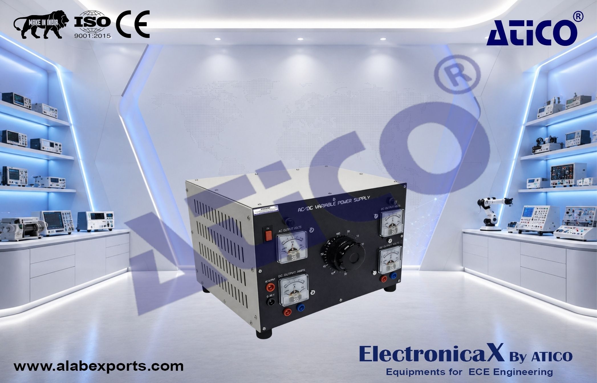
AC/DC Variable Power Supply
- Fixed Single Phase AC Power Supply: 240VAC, 50Hz
Adjustable Single Phase AC/DC Power Supply (Simultaneously) :
- – 0 ~ 250VAC, 0 ~ 12A AC
- – 0 ~ 230VDC, 0 ~ 12A DC
- AC/DC Voltmeter & AC/DC Ammeters provided to indicate output volts and amps.
AC Socket Outlet
- 2 nos. 13A / 250V AC switched socket outlets.
THREE PHASE POWER SUPPLY MODULE
- Modular Design
- Power Input: 3 Phase 240V/415V, 50Hz via input 5 core cable with 5 pin AC Plug, 32A.
- Connection: 3P+N+PE.
- Protection: Earth leakage circuit breaker and miniature circuit breaker
- Complete with START and STOP Push Button
- Three Pole ON/OFF Selector Switch.
- Unit Type : Panel H1
- Terminals: 4mm Safety Sockets
- Modular Design
- Connection: 3P+N+PE.
- Switch Load: 415Vac,10A
- Current Setting Range: 4 ~ 6.3A (Adjustable Current Limiting)
- Complete with START and STOP Push Button
- Unit Type : Panel H1
- Terminals: 4mm Safety Sockets (Color Coded)
CIRCUIT BREAKER (3 POLES) MODULE
- Modular Design
- Connection: 3P+N+PE
- Three Pole Circuit Breaker
- Switch Load: 10A
- Unit Type : Panel H1
- Terminals: 4mm Safety Sockets
- Modular Design
- 4 Units Pilot Lamp (Color: Red, Yellow, Blue & Green)
- Unit Type : Panel H1
- Terminals: 4mm Safety Socket
FUSE MODULE
- Modular Design
- Fuse Holder : 10 x 38: 4 Sets
- Fuse Rating : 10A
- Fuse Dimension : 10 x 38
- Unit Type : Panel H1
- Terminals: 4mm Safety Sockets (Color Coded)
- Modular Design
- 3 Pole Magnetic Contactor
- Auxiliary Switch (NCx2, NOx2)
- Unit Type : Panel H1
- Terminals: 4mm Safety Socket (Color Coded)
TIMER MODULE
- Modular Design
- Supply Voltage : 240VAC, 50Hz
- Time Range : 30 Sec
- Contact Rating : 240VAC, 5A
- Timer : 2 Units
- Timer 1 : Contact 1 (NCx1, NOx1);
- Contact 2 (NCx1, NOx1)
- Timer 2 : Contact 1 (NCx1, NOx1);
- Contact 2 (NCx1, NOx1)
- Unit Type : Panel H1
- Terminals: 4mm Safety Sockets
- Modular Design
- Push Button Switch 1 (NCx1, NOx1)
- Push Button Switch 2 (NCx1, NOx1)
- Push Button Switch 3 (NCx2)
- Push Button Switch 4 (NOx2)
- Unit Type : Panel H1
- Terminals: 4mm Safety Socket
SELECTOR SWITCH MODULE
- Modular Design
- Connection: 3P+N.
Switch 1: 4 Pole Selector Switch
- L1, L2, L3 and N
- Switch Load: 415Vac, 10A
Switch 2: 2 Way Selector Switch
- Way 1: Normally Close (NC)
- Way 2: Normally Open (NO)
- Switch Load: 240Vac, 5A
Switch 2: Key Switch
- Way 1: Normally Close (NC)
- Way 2: Normally Open (NO)
- Switch Load: 240Vac, 5A
- Terminals: 4mm Safety Sockets
- Modular Design
- Emergency Switch (NCx1, NOx1, Indicating Lamp)
- Alternate Push Button Switch 1 (NCx1, NOx1, Indicating Lamp)
- Alternate Push Button Switch 2 (NCx1, NOx1)
- Alternate Push Button Switch 3 (NCx1, NOx1)
- Current Rating : 5A
- Unit Type : Panel H1
- Terminals: 4mm Safety Sockets (Color Coded)
COUPLING HUB, NYLON SLEEVE & SAFETY GUARD
- Application: Motor & Generator
- Coupling Sleeve For Mechanical Connection Of Two Electrical Machines.
- Range: 5 to 99,999 RPM
Resolution:
- 0.1RPM 1000RPM
- Display: 5 Digits, 10mm (0.4–)LCD
- Accuracy: °0.05%+1 Digits
- Photo Detection Distance: 50 to 150mm
- Battery: 1.5V AA x 4 pcs
- Memory: Last Value, Max. Value, Min. Value
- Size: 190 x 72 x 37 mm
- Weight: 250g
ROTOR RESISTANCE STARTER UNIT
- Modular Design
- Power Rating (Suitable For Slip Ring Motor): From 1/2 – 5 Hp
- Rotor Resistance Step 1: 136 –
- Rotor Resistance Step 2: 68 –
- Steps: 2
- STAR Point: 1
- Modular Concept Design With 4mm Safety Socket : 12
- Unit Type: Panel H2
- Safety Terminal Socket : 4mm
- Type: 1.5KW (2 HP)
- Power Supply: Single phase 240V, 50Hz
- Power Terminals: R, S, T terminals
- Inverter Output: U, V, W
- Braking Resistor Terminals: P & B
- Panel Control Start/Stop, FWD and REV
- Terminal Control Start/Stop, FWD and REV
- Signal Input: 0-10V
- Digital Input: S1 to S5
- Analog Output: 4-20mA & AO
- Relay Output: RA–RB–RC
- Terminals : 4mm Safety Sockets
POWER DRIVE – SOFT STARTERS MODULE
- Modular Design
- Connection: TP+N
- Soft Starter: 2 Phase-Controlled 3 °, 415V
- Power Rating: 3HP, 4.8 A , Uc=110-230V AC/DC
- Unit Type : Panel H1
- Terminals: 4mm Safety Socket
- Modular design
- Measurement Range: 0% to 100%
- Protection: Fuse
- Unit Type : Panel H2
- Terminals: 4mm Safety Sockets (Color Coded)
EXPERIMENTS MODULE – POWER ELECTRONICS
GROUP OF DIODE MODULE
- Fast Acting Silicon Diode
- Voltage : 500V
- Current : 15A
- Safety Terminal Socket :4mm
- Unit Type : Panel H2
- Silicon Control Rectifier
- Voltage : 600V
- Current : 15A
- Safety Terminal Socket : 4mm
- Unit Type : Panel H2
TRIAC MODULE
- Voltage : 600V
- Current : 15A
- Safety Terminal Socket :4mm
- Unit Type : Panel H1
- Maximum DC Input Voltage : 220V
- Maximum DC Output Current : 5A
- Switching Frequency : 0–15KHz
- Safety Terminal Socket : 4mm
- Unit Type : Panel H1
DARLINGTON TRANSISTOR MODULE
- Darlington Transistor
- Maximum DC Input Voltage : 220V
- Maximum DC Output Current : 5A
- Switching Frequency : 0–15kH
- Safety Terminal Socket : 4mm
- Unit Type : Panel H1
- Insulated Gate Bipolar Transistor
- N-Channel enhancement mode silicon
- Maximum DC Input Voltage : 220V
- Maximum DC Output Current : 5A
- Switching Frequency : 0–15Kh
- Safety Terminal Socket : 4mm
- Unit Type : Panel H2
TWO PULSE CONTROLLER
- Power Supply : +15V/0V/-15V
- Input / Output : Transformer & Pulse Transformer
- Synchronization Voltage : 5-220V,50/60Hz
- Control Voltage (V) : 0-10V
- Trigger Angle : 0-30°
- Trigger Control Delay Angle : 0-180° & 180°-360°
- Pulse Output : Single Pulse, Train Pulse
- Safety Terminal Socket : 4mm
- Unit Type : Panel H1
- Power Supply : +15V/0V/-15V
- Input / Output : Transformer & Pulse
- Transformer
- Synchronization Voltage : 5-400V, 50/60Hz
- Control Voltage (V) : 0-10V
- Trigger Angle : 0-30°
- Trigger Control Delay Angle : 0-180° &
- 180°-360°
- Pulse Output : Single Pulse & Train Pulse
- Safety Terminal Socket : 4mm
- Unit Type : Panel H2
PWM CONTROLLER
- Pulse Width Modulation Isolated Pulse Output
- Frequency Variable : 0–20kHz : x1, x10, x100
- (Switchable)
- Duty Ratio : 0–100% (Reverse / Forward)
- Isolating Pulse Output : 4
- Safety Terminal Socket : 4mm
- Unit Type : Panel H2
- Power Supply : +15V/0V/-15V
- Synchronization Voltage : 5-400V,50/60Hz
- Output Phase Control : Positive and Negative
- Duty Cycle (D) : 0.00, 0.25, 0.50, 0.75, 1.00
- Safety Terminal Socket : 4mm
- Unit Type : Panel H1
RESISTIVE LOAD MODULE (I)
- Configuration : STAR , DELTA
- Resistor : 3X100Ohm / 100 Watt
- Fuse : Fast Acting
- Safety Terminal Socket : 4mm
- Unit Type : Panel H1
- Inductor : 50mH/2.5A
- Fuse : Fast Acting
- Safety Terminal Socket :4mm
- Unit Type : Panel H1
CAPACITOR LOAD MODULE
- Capacitor : 0.1uF / 450V
- Safety Terminal Socket :4mm
- Unit Type : Panel H1
- Resistor : 3x1Ohm/5Watt
- Safety Terminal Socket : 4mm
- Unit Type : Panel H1
DC POWER SUPPLY MODULE
- DC Fixed Output Voltage
- Short Circuit Protection
- Output Voltage : +15V/0/-15V
- Output Current : 2A
- Power Supply : 220V,50Hz
- Safety Terminal Socket : 4mm
- Unit Type : Panel H1
- The set consists of 2 type lead set and 2 type bridging plug set in 5 different coded colors and lengths chosen to allow the realization of all experiment manual.
- Leads are capable of 15A current safety plugs.
- Safety Terminal Socket (4mm): 25cm x 15 units; 50cm x 20 units; 100cm x 15 units
- 19mm Bridging Plug Set x 16 units
- 19mm Bridging Plug Set (Stackable) x 4 units
THREE PHASE AC POWER SUPPLY
- AC Fixed Output Voltage
- Short Circuit Protection
- AC Input Voltage: 3°240/415V+N+PE
- Transformer Output: 3°0-45-90V
- Output Current: 2.0A
- Circuit Breaker, E.L.C.B, Power Switch
- Fuse Fast Acting
- Safety Terminal Socket : 4mm
- Unit Type: Panel H4
EXPERIMENTAL TABLE
- 5– Workbench Table
- Material: 2mm Thickness 2– x 2– Hollow Steel Epoxy Coated
- 3 Layer Drawer With Centre Lock
- Heavy Duty Castor Wheel (Front With Lock)
Dimension:
- Length: 1500mm
- Width: 800mm
- Height: 850mm
- Din Standard A4 With Two Shelves
- Side Frame: T Shape
- Material: 2mm Thickness 1– x 2– Hollow Steel Epoxy Coated
Dimension:
- Length: 1450mm
- Width: 20mm
- Height: 300mm