ATENG 11410 — Advanced Mechanical, Electrical and Smart Grid Power Systems (Utilities)
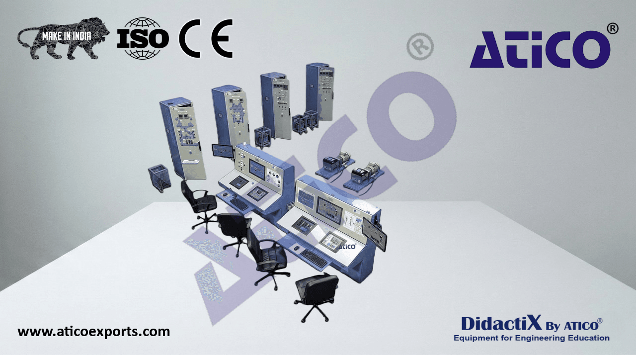
HUB II. Mechanical Power Plants and Energy System with SCADA II.
- Energy Control Desk:
Three touch screens for monitoring and control the power plants.
Panoramic screen.
Computer + keyboard + mouse.
Power cables and communication cable.
Magneto-thermal switches.
SCADA II system with computer control electronics and the proper
operation software package.
Communication interface with HUB I.
- 230 VAC Single-Phase power supply.
Interrupted power supply to support black out.
- Single-Phase residual circuit breaker 30mA / 230 VAC.
- Dimensions: 1600 x 840 x 1400 mm approx. (62.99 x 33.07 x 55.11 inches approx.)
Mechanical Control Bench
- Power Plants:
PPE/CC. Combined Cycle Power Plant.
PPE/NU. Nuclear Power Plant.
PPE/FD. Diesel Fuel Power Plant.
PPE/FF. Fossil Fuel (coals) Power Plant.
PPE/GA. Gas Power Plant.
PPE/HY. Hydroelectric Power Plant.
PPE/WP. Wind Powered Power Plant.
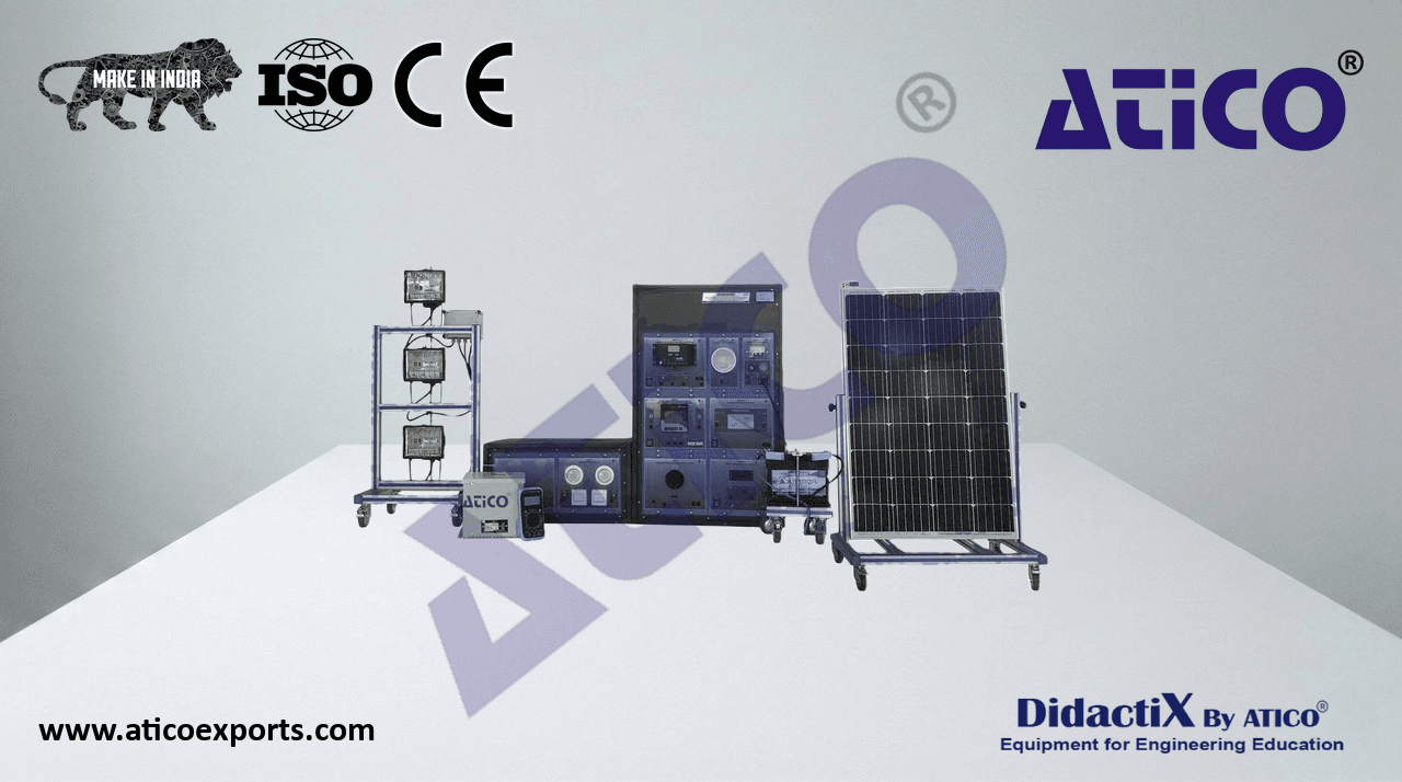
PPE/FV. Photovoltaic Power Plant.
PPE/HE. Heliothermic Power Plant.
PPE/BM. Biomass Power Plant.
PPE/FC. Fuel Cells Power Plant.
PPE/GT. Geothermal Power Plant.
Other power plants available on request.
HUB I. Electrical Power System with SCADA I.
- Electrical Control:
Three touch screens.
Panoramic screen.
Computer + keyboard + mouse.
Power cables and communication cable.
Magneto-thermal switches.
General emergency stop switch.
General emergency stop indicator.
Security key indicator.
Security key switch.
Generator manual synchronization push buttons.
Generator synchronizer devices.
Generator manual synchronization indicator.
Electrical Control Bench
Security keys for synchronization and fault insertion are included.
Programmable logic controller (PLC) with 42 I/O signals and
RS-485 communication interface.
Magneto-thermal switches.
Connectors of 6 and 24 pins.
4 ports RS232-RS485 converter.
SCADA I system with computer control electronics and the proper software
package for controlling the units of the system and to exchange information
with HUB II Power Plant Energy System and SCADA II.
- Dimensions: 1600 x 840 x 1400 mm approx. (62.99 x 33.07 x 55.11 inches approx.)
19
APS12-MES12.
Complete Advanced 12 Mechanical Power Plants (M) + Smart Grid Electrical Power Systems (E) + Smart Grid Distributed Load I (S)
Technical specifications
G1. Generator I with Complete Cabinet, including AVR (Automatic Voltage
Regulator), with Synchronization System.
Front panel diagram with signaling lamps to indicate the circuit breakers state.
Inductances for simulating the transient and sub-transient state of the generator.
- 400 VAC Three-Phase Power supply.
Current transformers.
Voltage transformers.
Vector inverter with automatic frequency load controller (AFLC).
Automatic/manual voltage regulator (AVR) and automatic/manual synchronization
device.
Magneto-thermal switches.
Power connectors.
- 3 x Power energy analyzers with RS-485 communication interface:
- Voltage: Range 20-500 Vrms. Prec.: 0.5%. Phase to phase-Phase to neutral. Current:
- Range 0.02-5 Arms. Prec.: 0.5%.
- Frequency: Range 48 to 62 Hz. 0.1Hz.
- Power: Active, Reactive and Apparent. Range 0.01 to 9900 kW. Prec.: 1%.
- Power Factor: Power Factor for each phase and average. Range -0.1 to + 0.1.
- Prec.: 1%.
Digital protection relays with RS-485 communication interface.
Differential protection relay.
Overcurrent protection relay.
Overvoltage/under voltage protection relay.
Directional protection relay.
Generator Rotor to Ground protection relay.
- Advanced Generator protection relay with AVR with the following protections:
Overcurrent protection threshold.
Over/under voltage protection threshold.
Reverse power protection threshold.
Over/under frequency protection threshold.
Unbalance protection threshold.
Programmable logic controller (PLC) with 42 I/O signals and RS-485 interfaces for
generation system topology configuration.
S7-300 PLC.
- 1 slot with 16 24 VDC digital inputs.
- 2 slots with 32 230 VAC digital outputs.
MPI communication cable.
55 Circuit breakers for generation switchgear maneuvers.
Power switches and fault state indicators in the front panel. G1. Generator I with Complete Cabinet,
Emergency stop included. including AVR (Automatic Voltage Regulator),
with Synchronization System
Back-up generation protection devices.
4 power connectors for energy distribution
2 62 pin signal connectors for communications.
- Dimensions: 1200 x 900 x 2000 mm approx. (47.24 x 35.43 x 78.74 inches approx.)
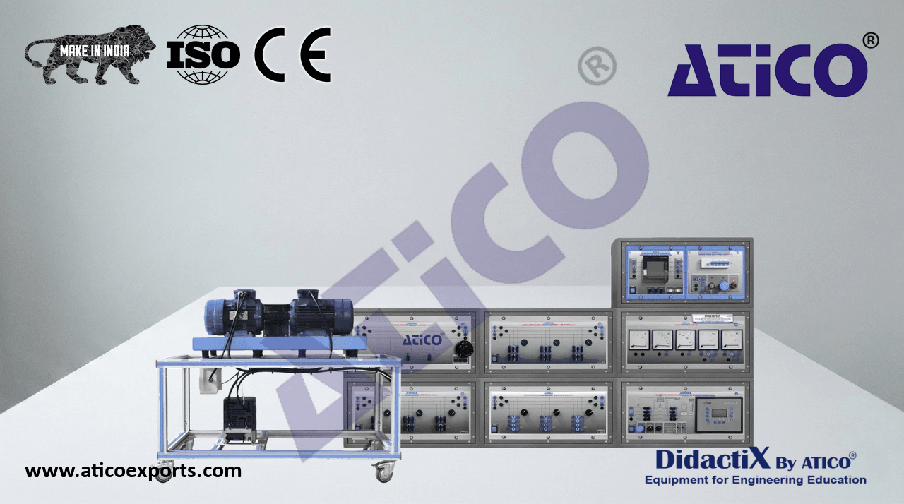
- Generator-Motor Group:
Base plate in painted steel and anodized aluminum structure with wheels for an easy
mobility.
- Three-Phase synchronous generator with brush excitation:
- Nominal Power: 7 kVA.
- Nominal Output Voltage: 230/400 VAC D/Y.
- Nominal Speed: 1500 rpm.
- Nominal frequency: 50/60 Hz.
- Power factor: 0.8.
- Motor prime mover:
Three-Phase squirrel cage motor.
- Nominal Power: 7 kVA.
- Nominal Output Voltage: 400 VAC.
- Nominal Speed: 1500 rpm. Generator-Motor Group
- Nominal frequency: 50/60 Hz.
Driven by a vector controller multifunction inverter with RS-485.
Semiflex coupling.
- Dimensions: 1300 x 450 x 450 mm approx. (51.18 x 17.71 x 17.71 inches approx.)
20
APS12-MES12.
Complete Advanced 12 Mechanical Power Plants (M) + Smart Grid Electrical Power Systems (E) + Smart Grid Distributed Load I (S)
Technical specifications
T-GR1. Grid Transformer without Voltage Regulation.
Three-phase power transformer.
- Primary voltage:400 VAC. Star.
- Secondary voltage: 400 VAC. Delta.
- Nominal Power: 5kVA.
Connection group Dy11.
Two power connectors.
Anodized aluminum structure and panels in painted steel with wheels for mobility.
- Dimensions: 400 x 360 x 600 mm approx. (15.74 x 14.17 x 23.62 inches approx.)
T-GR1. Grid Transformer without voltage regulation
T-G1. Generator Group Transformer I.
Three-phase power transformer.
- Primary voltage:400 VAC. Star
- Secondary voltage: 400 VAC. Delta
- Nominal Power: 5kVA.
Connection group Dy11.
Two power connectors.
Anodized aluminum structure and panels in painted steel with wheels for mobility.
- Dimensions: 400 x 360 x 600 mm approx. (15.74 x 14.17 x 23.62 inches approx.)
G2. Generator II with Complete Cabinet, including AVR (Automatic
Voltage Regulator), with Synchronization System.
Front panel diagram with signaling lamps to indicate the circuit breakers state.
T-G1. Generator Group Transformer I
Inductances for simulating the transient and sub-transient state of the generator.
- 400 VAC Three-Phase Power supply.
Current transformers.
Voltage transformers.
Vector inverter with automatic frequency load controller (AFLC).
Automatic/manual voltage regulator (AVR) and automatic/manual synchronization
device.
Magneto-thermal switches.
Power connectors.
- 3 x Power energy analyzers with RS-485 communication interface:
- Voltage: Range 20-500 Vrms. Prec.: 0.5%. Phase to phase-Phase to neutral Current:
- Range 0.02-5 Arms. Prec.: 0.5%.
- Frequency: Range 48 to 62 Hz. 0.1Hz.
- Power: Active, Reactive and Apparent. Range 0.01 to 9900 kW. Prec.: 1%.
- Power Factor: Power Factor for each phase and average. Range -0.1 to + 0.1.
- Prec.: 1%.
Digital protection relays with RS-485 communication interface.
Differential protection relay.
Overcurrent protection relay.
Overvoltage/under voltage protection relay.
Directional protection relay.
Generator Rotor to Ground protection relay.
- Advanced Generator protection relay with AVR with the following protections:
Overcurrent protection threshold.
Over/under voltage protection threshold.
Reverse power protection threshold.
Over/under frequency protection threshold.
Unbalance protection threshold.
Programmable logic controller (PLC) with 42 I/O signals and RS-485 interfaces
for generation system topology configuration.
S7-300 PLC.
- 1 slot with 16 24 VDC digital inputs.
- 2 slots with 32 230 VAC digital outputs.
MPI communication cable.
55 Circuit breakers for generation switchgear maneuvers.
Power switches and fault state indicators in the front panel.
Emergency stop included.
Back-up generation protection devices.
4 power connectors for energy distribution
G2. Generator II with Complete Cabinet,
2 62 pin signal connectors for communications.
including AVR (Automatic Voltage Regulator),
- Dimensions: 1200 x 900 x 2000 mm approx. (47.24 x 35.43 x 78.74 inches approx.) with Synchronization System
21
APS12-MES12.
Complete Advanced 12 Mechanical Power Plants (M) + Smart Grid Electrical Power Systems (E) + Smart Grid Distributed Load I (S)
Technical specifications
- Generator-Motor Group:
Base plate in painted steel and anodized aluminum structure with wheels for an easy
movement.
- Three-Phase synchronous generator with brush excitation:
- Nominal Power: 7 kVA.
- Nominal Output Voltage: 230/400 VAC D/Y.
- Nominal Speed: 1500 rpm.
- Nominal frequency: 50/60 Hz.
- Power factor: 0,8
- Motor prime mover:
Three-Phase squirrel cage motor.
- Nominal Power: 7 kVA. Generator-Motor Group
- Nominal Output Voltage: 400 VAC.
- Nominal Speed: 1500 rpm.
- Nominal frequency: 50/60 Hz.
Driven by a vector controller multifunction inverter with RS-485.
Semiflex coupling.
- Dimensions: 1300 x 450 x 450 mm approx. (51.18 x 17.71 x 17.71 inches approx.)
T-G2. Generator Group Transformer II.
Three-phase power transformer.
- Primary voltage:400 VAC. Star.
- Secondary voltage: 400 VAC. Delta.
- Nominal Power: 5kVA.
Connection group Dy11.
Two power connectors. T-G2. Generator Group Transformer II
Anodized aluminum structure and panels in painted steel with wheels for mobility.
- Dimensions: 400 x 360 x 600 mm approx. (15.74 x 14.17 x 23.62 inches approx.)
LTS1. Line I and II Cabinet with Transmission Substation with Protection
Relays System.
Front panel diagram with signaling lamps to indicate the circuit breakers state.
Inductances, capacitors and resistors. It includes tapping points for changing the length
of lines and the configuration of PI or T line loss profiling, and fault injection with the
help of PLC control device.
- 400 VAC Three-Phase Power supply.
Current transformers.
Voltage transformers.
Magneto-thermal switches.
Power connectors.
- 2 x Power energy analyzers with RS-485 communication interface for Line 1 and Line 2:
- Voltage: Range 20-500 Vrms. Prec.: 0.5%. Phase to phase-Phase to neutral. Current:
- Range 0.02-5 Arms. Prec.: 0.5%.
- Frequency: Range 48 to 62 Hz. 0.1Hz.
- Power: Active, Reactive and Apparent. Range 0.01 to 9900 kW. Prec.: 1%.
- Power Factor: Power Factor for each phase and average. Range -0.1 to + 0.1. Prec.:
1%.
Digital protection relays with RS-485 communication interface.
Distance protection relay.
Overcurrent protection relay.
Overvoltage/under voltage protection relay.
Directional protection relay.
Programmable logic controller (PLC) with 42 I/O signals and RS-485 interfaces for
generation system topology configuration.
S7-300 PLC.
- 1 slot with 16 24 VDC digital inputs.
- 2 slots with 32 230 VAC digital outputs.
MPI communication cable.
65 Circuit breakers for generation maneuvers.
Power switches and fault state indicators in the front panel.
Emergency stop included.
Back-up protection devices.
4 power connectors for energy distribution.
2 62 pin signal connectors for communications.
LTS1. Line I and II Cabinet with Transmission
- Dimensions: 1200 x 900 x 2000 mm approx. (47.24 x 35.43 x 78.74 inches approx.) Substation with Protection Relays System
22
APS12-MES12.
Complete Advanced 12 Mechanical Power Plants (M) + Smart Grid Electrical Power Systems (E) + Smart Grid Distributed Load I (S)
Technical specifications
LTS2. Line III and IV Cabinet with Transmission Substation with Protection
Relays System.
Front panel diagram with signaling lamps to indicate the circuit breakers state.
Inductances, capacitors and resistors. It includes tapping points for changing the length
of lines and the configuration of PI or T line loss profiling, and fault injection with the help
of PLC control device.
- 400 VAC Three-Phase Power supply.
Current transformers.
Voltage transformers.
Magneto-thermal switches.
Power connectors.
- 2 x Power energy analyzers with RS-485 communication interface for Line 1 and Line 2:
- Voltage: Range 20-500 Vrms. Prec.: 0.5%. Phase to phase-Phase to neutral. Current:
- Range 0.02-5 Arms. Prec.: 0.5%.
- Frequency: Range 48 to 62 Hz. 0.1Hz.
- Power: Active, Reactive and Apparent. Range 0.01 to 9900 kW. Prec.: 1%.
- Power Factor: Power Factor for each phase and average. Range -0.1 to + 0.1. Prec.:
1%.
Digital protection relays with RS-485 communication interface.
Distance protection relay.
Overcurrent protection relay.
Overvoltage/under voltage protection relay.
Directional protection relay.
Programmable logic controller (PLC) with 42 I/O signals and RS-485 interfaces for
generation system topology configuration.
S7-300 PLC.
- 1 slot with 16 24 VDC digital inputs.
- 2 slots with 32 230 VAC digital outputs.
MPI communication cable.
65 Circuit breakers for tansmission switchgear maneuvers.
Power switches and fault state indicators in the front panel.
Emergency stop included.
Back-up protection devices. LTS2. Line III and IV Cabinet with Transmission
Substation with Protection Relays System
4 power connectors for energy distribution
2 62 pin signal connectors for communications.
- Dimensions: 1200 x 900 x 2000 mm approx. (47.24 x 35.43 x 78.74 inches approx.)
DSL1. Distribution Substation I, Loads and Network Equivalents I with
Protection Relays System.
Front panel diagram with signaling lamps to indicate the circuit breakers state.
Inductances, capacitors and resistors for different energy consumption.
- 400 VAC Three-Phase Power supply.
Current transformers.
Voltage transformers.
Magneto-thermal switches.
Power connectors.
- 2 x Power energy analyzers with RS-485 communication interface for Line 1 and Line 2:
- Voltage: Range 20-500 Vrms. Prec.: 0.5%. Phase to phase-Phase to neutral. Current:
- Range 0.02-5 Arms. Prec.: 0.5%.
- Frequency: Range 48 to 62 Hz. 0.1Hz.
- Power: Active, Reactive and Apparent. Range 0.01 to 9900 kW. Prec.: 1%.
- Power Factor: Power Factor for each phase and average. Range -0.1 to + 0.1. Prec.:1%.
Digital protection relays with RS-485 communication interface.
Differential protection relay.
Overcurrent protection relay.
Overvoltage/under voltage protection relay.
Directional protection relay.
Programmable logic controller (PLC) with 42 I/O signals and RS-485 interfaces for
generation system topology configuration.
S7-300 PLC.
- 1 slot with 16 24 VDC digital inputs.
- 2 slots with 32 230 VAC digital outputs.
MPI communication cable.
65 Circuit breakers for distribution and consumption switchgear maneuvers.
Power switches and fault state indicators in the front panel.
Emergency stop included.
Back-up protection devices.
4 power connectors for energy distribution.
2 62 pin signal connectors for communications. DSL1. Distribution Substation I, Loads and Network
Equivalents I with Protection Relays System
- Dimensions: 1200 x 900 x 2000 mm approx. (47.24 x 35.43 x 78.74 inches approx.)
23
APS12-MES12.
Complete Advanced 12 Mechanical Power Plants (M) + Smart Grid Electrical Power Systems (E) + Smart Grid Distributed Load I (S)
Technical specifications
T-GR2. Grid Transformer with TAP CHANGER with Voltage Regulation.
Three-phase power transformer.
- Primary voltage:400 VAC. Delta
- Secondary voltage: 400 VAC. Star
- Nominal Power: 5kVA.
Connection group Dy11.
Two power connectors.
- Automatic TAP voltage regulator: -7,5% /-2,5% / 0% /+2,5% /+5% /+7,5%.
Anodized aluminum structure and panels in painted steel with wheels for mobility.
- Dimensions: 400 x 360 x 600 mm approx. (15.74 x 14.17 x 23.62 inches approx.)
T-GR2. Grid Transformer with TAP CHANGER
with voltage regulation
DSL2. Distribution Substation II, Loads and Network Equivalents II
with Protection Relays System.
Front panel diagram with signaling lamps to indicate the circuit breakers state.
Inductances, capacitors and resistors for different energy consumption.
- 400 VAC Three-Phase Power supply.
Current transformers.
Voltage transformers.
Magneto-thermal switches.
Power connectors.
- 2 x Power energy analyzers with RS-485 communication interface for Line 1 and Line 2:
- Voltage: Range 20-500 Vrms. Prec.: 0.5%. Phase to phase-Phase to neutral.
- Current: Range 0.02-5 Arms. Prec.: 0.5%.
- Frequency: Range 48 to 62 Hz. 0.1Hz.
- Power: Active, Reactive and Apparent. Range 0.01 to 9900 kW. Prec.: 1%.
- Power Factor: Power Factor for each phase and average. Range -0.1 to +
- 0.1. Prec.: 1%.
Digital protection relays with RS-485 communication interface.
Differential protection relay.
Overcurrent protection relay.
Overvoltage/under voltage protection relay.
Directional protection relay.
Programmable logic controller (PLC) with 42 I/O signals and RS-485 interfaces
for generation system topology configuration.
S7-300 PLC.
- 1 slot with 16 24 VDC digital inputs.
- 2 slots with 32 230 VAC digital outputs.
MPI communication cable.
65 Circuit breakers for generation maneuvers.
Power switches and fault state indicators in the front panel.
Emergency stop included.
DSL2. Distribution Substation II, Loads and
Back-up protection devices. Network Equivalents II with Protection Relays
System
4 power connectors for energy distribution
2 62 pin signal connectors for communications.
- Dimensions: 1200 x 900 x 2000 mm approx. (47.24 x 35.43 x 78.74 inches approx.)
24
APS12-MES12.
Complete Advanced 12 Mechanical Power Plants (M) + Smart Grid Electrical Power Systems (E) + Smart Grid Distributed Load I (S)
Technical specifications
SGDL1. Smart Grid Distributed Load I.
Front panel energy distribution diagram with signaling lamps to indicate the loads state.
Inductances and resistors for different final user energy consumption.
- 400 VAC Three-Phase Power supply.
Current transformers.
Magneto-thermal switches.
Power connectors.
3 x Power energy analyzers with RS-485 communication interface for Industrial Load,
Residential Load 1 and Residential Load 2.
- Voltage: Range 20-500 Vrms. Prec.: 0.5%. Phase to phase-Phase to neutral. Current:
- Range 0.02-5 Arms. Prec.: 0.5%.
- Frequency: Range 48 to 62 Hz. 0.1Hz.
- Power: Active, Reactive and Apparent. Range 0.01 to 9900 kW. Prec.: 1%.
- Power Factor: Power Factor for each phase and average. Range -0.1 to + 0.1. Prec.:
1%.
- Three-Phase Automatic Power Factor Compensator: six compensation steps / power set point.
3 x Three Phase Smart Meters.
1 x Three Phase Data Concentrator with power line communication.
Programmable logic controller (PLC) with 42 I/O signals and RS-485 interfaces for
generation system topology configuration.
S7-300 PLC.
- 1 slot with 16 24 VDC digital inputs.
- 1 slots with 32 230 VAC digital outputs.
MPI communication cable.
Circuit breakers for load maneuvers.
Power switches and fault state indicators in the front panel.
Emergency stop included.
Back-up protection devices.
SGDL1. Smart Grid Distributed Load I
4 power connectors for energy distribution
2 62 pin signal connectors for communications.
- Dimensions: 1200 x 900 x 2000 mm approx. (47.24 x 35.43 x 78.74 inches approx.)
T-D1. Distribution Transformer I.
Three-phase power transformer.
- Primary voltage:400 VAC. Star.
- Secondary voltage: 400 VAC. Delta.
- Nominal Power: 5kVA.
Connection group Dy11.
Two power connectors.
Anodized aluminum structure and panels in painted steel with wheels for mobility.
- Dimensions: 400 x 360 x 600 mm approx. (15.74 x 14.17 x 23.62 inches approx.)
T-D1. Distribution Transformer I
- For details see Annex IV:
- Specifications subject to change without previous notice, due to the convenience of improvements of the product.