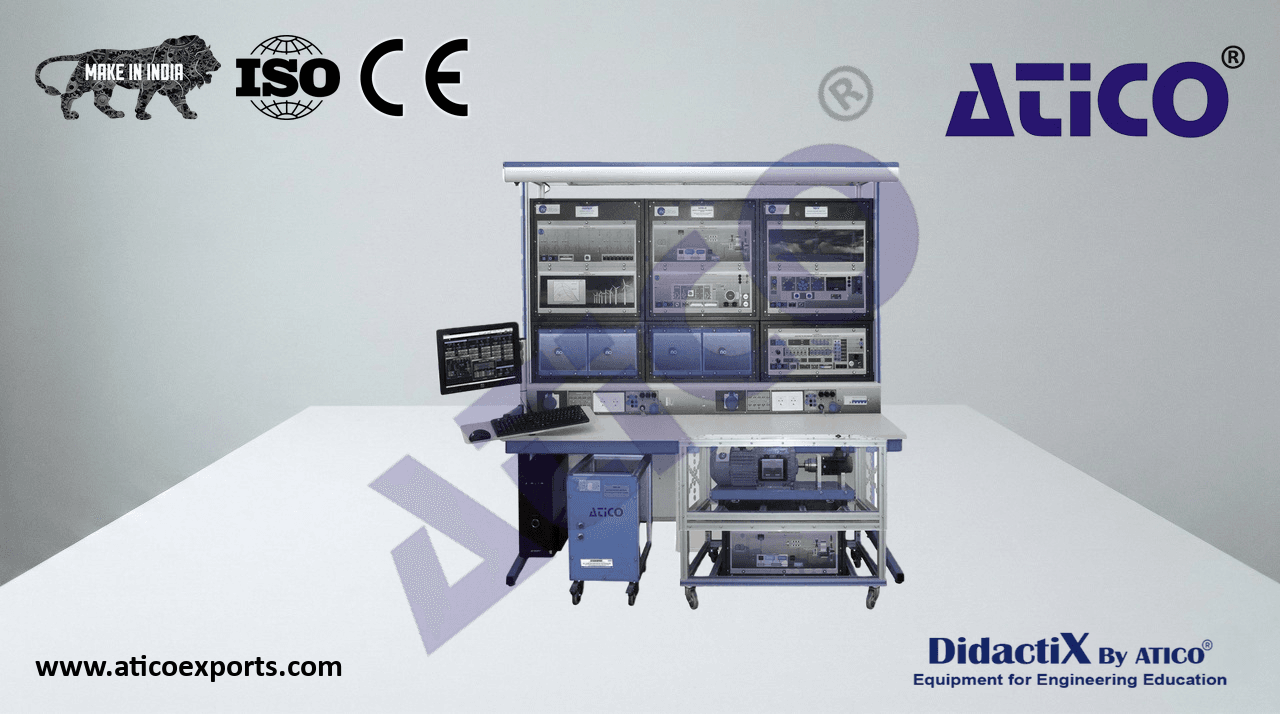
ATENG 11411 — Modular Smart Grid Power Systems Series
at the end of this catalog.
b) POWER TRANSMISSION INCLUDED ELEMENTS AEL-WBMG. Electrical Workbench (Mobile Big).
N-ALI01. Industrial Main Power Supply.
N-EALD. Network Analyzer Module with Oscilloscope and Data
Acquisition (2 units).
N-AE1CD. Transmission Lines Simulation Digital Unit (2 units).
N-REG16. Voltage Regulation Module 1.
TRANS3/5KRM. Three-Phase Autotransformer with Motor
- Voltage Regulator, 400/400 VAC, 5 kVA.
- Protection Relays for Transmission Lines:
- N-ERP-PD01. Distance Protection Relay Module.
- N-ERP-MF01. Digital Fault Simulator Module.
- N-PSM. Power Switch Module (2 units).
- Technical specifications at the end of this catalog.
c) POWER DISTRIBUTION AND LOADS INCLUDED ELEMENTS N-ALI01. Industrial Main Power Supply.
N-EALD. Network Analyzer Module with Oscilloscope and Data
Acquisition (2 units).
N-BUS08. Distribution Busbar Module (4 units).
N-BUS09. Coupling Busbar Module.
- PFC-KIT. Power Factor Controller Kit:
- N-CFP. Advanced Power Factor Controller Module.
- N-CAR19T4D. Three-phase Digital capacitor Banks Module.
Protection Relays for Distribution and Loads.
- N-ERP-MA01. Feeder Management Relay Module.
- N-ERP-MF01. Digital Fault Simulator Module.
AEL-WBMG. Electrical Workbench (Mobile Big).
- Technical specifications at the end of this catalog.
d) RENEWABLE AND CONVENTIONAL ENERGIES INCLUDED
ELEMENTS
- h- tAtpEsL:/-/PwHwVwG.eCd. iCboomn.cpoumte/er nC/oconmtropluletedr -Pchoonttroovloleltda-ipch Pootowveorlt aic-
power-plants-apPplalincatsti oAnpplication
- h-tAtpEsL:/-/WwPwPwIC.e.d Wibionnd.c oPmow/eenr/ wPlianndt-sp owwitehr- pInladnutcst-wiointh G-ienndeurcattioonr -
generator-applicAaptiponlic-watitiohn-s,c waditah SCADA.
- h-TtDtpEsG://Cw. wCwo.emdipbuotne.cr omCo/ennt/rcoollmedp utDeire-cseoln trEonllgeidn-ed ieEselel-ctrical ATENG 11483
engine-eleGcternicearla-gtoenr eArpatpolric-aaptipolnic.ation ATENG 11435
ATENG 12385
ATENG 11411 Modular Smart Grid Power Systems Series
- e) REQUIRED ELEMENTS (AT LEAST ONE) (NOT INCLUDED): -N-CAR19T3D. Three-phase Digital Bank of Commutable
Capacitors Module.
TPEL/1800W. Single-phase AC/DC Electronic Load of
1800W (3 units). -N-CAR35T3D. Three-phase Digital Bank of Commutable
Resistors Module.
- RCL-KIT-1C. Loads Kit with SCADA Control:
- N-CAR36T3D. Three-phase Digital Bank of Commutable
Inductances Module.
- Technical specifications at the end of this catalog.
f)ADDITIONAL RECOMMENDED ELEMENTS (AT LEAST ONE) ATENG 11420. Geothermal Power Plants Simulator.
- (NOT INCLUDED): TPEL/1800W. Single-phase AC/DC Electronic Load of
ATENG 11419. Biomass Power Plants Simulator.
1800W (3 units).
ATENG 11416. Gas Power Plants Simulator.
ATENG 11414. Hydroelectric Power Plants Simulator.
ATENG 11422. Heliothermic Solar Power Plants Simulator.
ATENG 11417. Wind Powered Power Plants Simulator.
EXERCISES & PRACTICAL POSSIBILITIES
1.- Study of g1.e- nSeturadtyio onf, gtreannesrmatiisosnio, ntr aannsdm diissstiroibnu atniodn d pisotwriberu styiosnte pmosw. er systems.
2.- Analysis o2.f- tAhnea mlyesiass oufr ethmee mntesa osfu trheme peonwtse or ffl tohwe sp oofw tehre fl soywncsh orfo tnhoeu ssy gnecnherorantoour,s t graennsemraistosiro, ntr alinnsems aisnsdio lno alidnes.s and loads.
3.- Analysis 3o.f- tAhnea alycstiisv eo fa tnhde r aecatcitviev ea npdo wreearc otfiv teh pe oswynecrh orfo tnhoeu ssy gnecnherorantoour sa ggeainnesrta ltooard a gvaariniastti olonasd. variations.
4.- Automat4ic.- sAyuntcohmroantiizca styionnch mroanniezautvieorns mof asnyneuchverorsn oofu ssy gnecnherorantoour sw gitehn ethraet omr awinitsh. the mains.
5.- Study of 5th.-e S styundcyh orof nthoeu ssy gnecnherroantooru isn g ieslnaenrda toopr einra itsiloann dm oopdeer.a tion mode.
6.- Study of 6th.- eS Mtuidcyro o-fG trhides M. icro-Grids.
7.- Study of 7th.- eS stuyndcyh orfo tnhoeu ssy gnecnherorantoour sin g genriedr aptaorra lilne lg oripde praatriaolnle ml oopdeera. tion mode.
8.- Study of e8x.-c Sittautdioy no/fv eoxltcaigtaet iroeng/uvloalttiaogne o rfe sgyunlachtiroonn oofu ssy gnecnherorantoour sin g iesnlaenradt omr oind eis. land mode.
9.- Study of 9tu.-r bSitnued rye ogfu tluartbioinne (f rreegquuleanticoyn c (ofrnetqroule) ninc yis claonndtr mol)o idne is. land mode.
10.-Study of1 0ex.-cSittautdioy no/fv eoxltcaigtaet iroeng/uvloalttiaogne o rfe sgyunlachtiroonn oofu ssy gnecnherorantoour sin g penarearlaletol rg irnid p oapraelrlaetl igornid m oopdeera. tion mode.
11.-Study of 1t1u.-rSbtiunde yr eogf utulartbioinne ( frreegquulaetniocny c(forenqtruoel)n icny p caornaltlreoll )g irnid p oapraelrlaetl igornid m oopdeera. tion mode.
12.-Study of1 t2h.-eS ptuodwye or ff athceto pr orewgeurl afatciotonr o rfe sgyunlachtiroonn oofu ssy gnecnherorantoour sin g penarearlaletol rg irnid p oapraelrlaetl igornid m oopdeera. tion mode.
13.-Analysis 1a3n.-dA ncaallcyusilsu as nodf ecnaelcruglyu lso osef se nine rtgrayn lsomseiss siino ntr alinnsems aiscscioonrd liinnges t oa ctchoer dlinineg e tloe ctthreic lainl pe aerlaemcteritcearls p. arameters.
14.-Capaciti1v4e. -eCffaepcatc initflivuee enfcfeec itn i ntrflaunesnmcies siino ntr alinnsems. ission lines.
15.-Analysis 1o5f. -tAhnea rleyasicst iovfe t ehnee rregayc etixvcee esns einrg tyra enxscmesiss siino ntr alinnsems. ission lines.
16.-Analysis 1o6f. -tAhnea ilnyflsiuse onfc teh eo fi noflnuee onrc me oofr eo nlinee o lro mssoerse i nli nthe elo eslseecst riinc tshyest eelmec. tric system.
17.-Power fa1c7t.o-Pr ocwomerp faecntsoart icoonm apnedn tshaet ieofnfe acntds itnh teh ATENG 12232 fpeocwtse irn s tyhsete pmo.wer system.
18.-Single-P1o8le.-,S Tinwgol-eP-Poloel ea,n Tdw toh-Preoele-P aonled ftahurletse -wPiothle afanudl tws iwthitohu at nimd pweidthaonucte.i mpedance.
19.-Double b19u.s-D boaur bcoleu bpulisn gb amr caonuepuvlienrg. maneuver.
20.-Operatio2n0.l-oOgpice rwatitiohn c ilrocguicit wbriteha kceirrcsu aitn bdr deiaskceornsn aencdto driss cino nan deocutobrles ibnu as dboaur bsuleb bstuast iboanr. substation.
21.-Load sha2r1in.-Lgo wadit hsh daifrfinerge wnti tfhe eddifefersr.e nt feeders.
22.-Bus bar 2c2h.a-Bnugse obvaerr c whaitnhgoeuot vienrt ewrrituhpotuiotn in. terruption.
- Some practSicoaml eex perraccisteicsa ATENG 11636 oesxseirbciilsiteise sp wosisthib tilhitei eSsC wAiDthA :t he SCADA:
23.-Remote2ly3 c.-oRnetmrool toefl yg econnertarotilo onf pgeonweerra stiyosnte pmosw. er systems.
24.-Analysis2 w4.i-tAhn tahley sSisC wADitAh tshoeft wSCaAreD oAf ssoynftcwharroen oofu ssy gnecnherorantoour sp goewneerr flatoowr sp. ower flows.
25.-Analysis2 w5.i-tAhn SaClyAsDisA w siothft wSCaAreD oAf saocfttiwvea aren dof r aecatcitviev ea npdo wreearc otfiv sey npcohwreorn oofu ssy gnecnherorantoour.s generator.
26.-Remote2ly6 c.-oRnetmrool toefl ym caonnutraol ls oynf mcharnonuaizla styionnch orfo snyinzachtiroonn oofu ssy gnecnherorantoour sw gitehn ethraet omr awinitsh. the mains.
27.-Remote2ly7 c.-oRnetmrool toefl ya ucotonmtroatl iocf s ayuntcohmroantiizca styionnch orfo snyinzachtiroonn oofu ssy gnecnherorantoour sw gitehn ethraet omr awinitsh. the mains.
28.-Remote2ly8 c.-oRnetmrool toefl ys ycnocnhtrroonl oofu ssy gnecnherorantoour sin g iesnlaenradt ogrr iidn oisplaenradt igornid m oopdeera. tion mode.
29.-Study of2 M9.-icSrtou-dGyr iodfs M. icro-Grids.
30.-Remote3ly0 c.-oRnetmrool toefl ys ycnocnhtrroonl oofu ssy gnecnherorantoour sin g penarearlaletol rg irnid p oapraelrlaetl igornid m oopdeera. tion mode.
31.-Remotel3y1 c.-oRnetmrool toefl ye xccointatrtoiol no/fv eoxltcaigtaet iroeng/uvloalttiaogne o rfe sgyunlachtiroonn oofu ssy gnecnherorantoour sin g iesnlaenradt omr oind eis.land mode.
ATENG 11411 Modular Smart Grid Power Systems Series
- Some practSicoaml eex perraccisteicsa ATENG 11636 oesxseirbciilsiteise sp wosisthib tilhitei eCso wmipthu ttehre C Coonmtrpoullteedr PChoonttorovloleltda iPch Pootwoveorl Ptalaicn Ptso Awpepr lPiclaantitosn A, “pApEliLc-aPtHioVnG, “CA”:E L-PHVGC”:
32.-Measure3m2.e-Mnte aansudr ecmalceunlta atinodn coaf ltchuela atciotinv eo fp tohwee arc ctoivnes pumoweedr bcyo nas tuhmreeed-p bhya ase t hvraeriea-bplhea rsees ivsatirviaeb lolea rde. sistive load.
33.-Measure3m3.e-Mnte aansudr ecmalceunlta atinodn coaf ltchuela ttoiotanl opfo twheer t cootanls pumoweedr bcyo nas tuhmreeed-p bhya ase t hRr-eLe l-opahda. se R-L load.
34.-Configu3ra4t.i-oCno nofif gthuera ptrioong roafm thmea pbrloeg praomwemr asubplep plyo awse Pr Vsu Aprpralyy.a s PV Array.
35.-Maximu3m5. -pMroadxuimctuiomn porfo pdhuocttoiovonl toafi cp hpootwoveor lwtaitich pgoriwde inr jwecitthio gnr itdh rinojuegchti othne t hgrroidu ginhv ethrtee rg. rid inverter.
36.-Maximu3m6. -pMroadxuimctuiomn porfo pdhuocttoiovonl toafi cp hpootwoveor lwtaitich pgoriwde inr jwecitthio gnr iadn idn jleocctaiol enn aenrdg yl occoanl seunmerpgtyio cno.n sumption.
37.-Dynamic3 7c.o-Dnytrnoalm ofi ca cctoivnetr pool owfe arc wtiivteh pthoew perh wotiothvo tlhtaei cp hinovteorvtoelrt. aZice rion vinejretecrt.i oZne rcoo inntjreoclt. ion control.
38.-Dynami3c8 c.o-Dnytrnoalm ofi ca cctoivnetr pool owfe arc wtiivteh pthoew perh wotiothvo tlhtaei cp hinovteorvtoelrt. aGicri din ivnejretcetri.o Gnr icdo inntjreoclt. ion control.
39.-Static co3n9t.-rSotl aotfi ca cctoivnetr pool owfe arc wtiivteh pthoew perh wotiothvo tlhtaei cp hpootwoveor.l tCaoicn fipgouwraetri. oCno nofif gcounrattroioln c oonf dcoitniotnrosl wcoitnhd ditiigointasl wsiigthn adlsig. ital signals.
40.-Experim4e0n.-tEaxl pcaelrcimuleantitoanl coaf lIc-Vu lcautirovne ooff Ia-V p chuortvoev oolft aai cp hpoatnoevlo. ltaic panel.
41.-Variation4 1o.-f Vsaorliaart rioand ioaft isoonla wr irtahd tiahteio hna lwoigtehn t hlaem hpaslo pgaenne lla. mMepass puarenmel.e Mnte oasf uI-rVe mcheanrta cotfe Ir-iVs tcichsa.racteristics.
- Some practicSaolm exee prcraiscetsic paol sesxiebricliitsieess pwoitshsi tbhileit Wiesin wdi Ptho wtheer WPlianndt sP wowitehr I Pnldauncttsi owni tGhe Innedruacttoiro An pGpelniceartaitoonr, Awpitphl iScaCtAioDnA, w “AitEhL S-WCAPDPAIC, ”“:A EL-WPPIC”:
42.-Commis4s2io.-nCionmg omf itshsieo innidnug cotfi otnh eg ienndeuracttoiorn. generator.
43.-Wiring p4r3o.c-Wediruinreg o pfr tohcee dinudrue cotfi otnh eg ienndeuracttoiorn t og ethnee rgartiodr. to the grid.
44.-Study of4 o4p.-eSrtautdioyn o rf eogpimeraetsi oonf trheeg iwminesd otfu trhbein wesin wdi tthu rtbhirneeesp whaitshe tihnrdeuecpthioans eg ienndeuracttoiorn o gf esqnueirrarteol rc oafg seq. uirrel cage.
45.-Analysis4 o5f. -tAhnea ilnydsius cotfi otnh eg ienndeuracttoiorns cgoeunpelreadto tros tchoeu pgrleidd itno s tuhbe- sgyrnidc hinr osnuobu-ssy sntcahtero. nous state.
46.-Analysis4 o6f. -tAhnea ilnydsius cotfi otnh eg ienndeuracttoiorns cgoeunpelreadto tros tchoeu pgrleidd itno s tyhnec hgrriodn ionu ssy sntcahtero. nous state.
47.-Analysis4 o7f. -tAhnea ilnydsius cotfi otnh eg ienndeuracttoiorns cgoeunpelreadto tros tchoeu pgrleidd itno s tuhpee gr-rsidyn inch sruopneoru-ssy sntcahtero. nous state.
48.-Study of4 e8l.e-Sctturidcay lo pf aerlaemcteritcearls p oaf rtahme eintedrus cotfi otnh eg ienndeuracttoiorn c oguenpelerdat toor tchoeu pgrleidd itno s tuhbe- sgyrnidc hinr osnuobu-ssy sntcahtero. nous state.
49.-Study of4 e9l.e-Sctturidcay lo pf aerlaemcteritcearls p oaf rtahme eintedrus cotfi otnh eg ienndeuracttoiorn c oguenpelerdat toor tchoeu pgrleidd itno s tyhnec hgrriodn ionu ssy sntcahtero. nous state.
50.-Study o5f 0el.e-Sctturidcay lo pf aerlaemcteritcearls p oaf rtahme eintedrus cotfi otnh eg ienndeuracttoiorn c oguenpelerdat toor tchoeu pgrleidd itno s tuhpee gr-rsidyn inch sruopneoru-ssy sntcahtero. nous state.
51.-Efficienc5y1 s.-tEufdfiyc ioefn tchye s itnudduyc otfio tnh eg ienndeuracttoiorn c ogmenpeararitnogr cthoem inpjaercintegd t hpeo winejer cinte tdh ep ogwrider w init thh teh ger mid ewcihthan tihcea lm peocwhearn sihcaafl tp oofw theer shaft of the
turbine. turbine.
52.-Power fa5c2t.-oPro iwnfleur efanccteo rw iinthfl utehnec sep weeitdh vtahreia stipoenesd a vnadr iaatniaolnyss isa nodf tahnea lpyosisss iobfl eth seo lpuotisosnibsl eto s oaluuttoiomnast eto t haue troemgualtaet itohne oref gthuela tion of the
power factopr.o wer factor.
53.-Active p5o3w.-eArc ctoivme ppeonwseart icoonm bpye mnseaatnio cna bpya cmiteoar nb acnapksa caintodr ebleacntkrsic aanl dm eelaescutrreicmale mnte oasf uthreem eleenctt roicf athl me ealcehcitnriec arel smpaocnhsein.e response.
- Some practSicoaml eex perraccisteicsa ATENG 11636 oesxseirbciilsiteise sp wosisthib tilhitei eCso wmipthu ttehre C Coonmtrpoullteedr DCoiensterlo Ellnegdi nDeie Esleelc Etnrigcainl eG Eelneecrtarticoar lA Gpepnleicraattioorn A, “pTpDliEcGatCio”:n, “ATENG 11435”:
54.-Automa5ti4c. -sApueteodm caotnict rsopl eoefd t hceo netnrgoiln oef athned egnegnienrea taonrd in g iesnlaenradt.or in island.
55.-Manual 5sp5.e-Meda ncounatl rsopl eoefd t hceo netnrgoiln oef itnh eis leanngdi.ne in island.
56.-Automa5ti6c. -eAxucittoamtioanti cc oenxctriotal toiof nth ceo tnhtrreoel -opf hthasee t hsyrneech-prohnasoeu ssy gnecnherroantooru.s generator.
57.-Manual 5e7xc.-iMtaatniouna lc oexnctirtoalt oiofn t hceo nthtrroele o-pf hthaese t hsyrenec-hprhoansoeu ssy gnecnherorantoour.s generator.
58.-Automa5ti8c. -sApueteodm caotnict rsopl eoefd t hceo netnrgoiln oef itnh ep aernagllienle w init hp athrael lgerl iwd.ith the grid.
59.-Manual 5s9p.e-Meda ncounatl rsopl eoefd t hceo netnrgoiln oef itnh ep aernagllienle w init hp athrael lgerl iwd.ith the grid.
60.-Automa6t0ic. -eAxuctiotamtioatnic c oexnctirtoalt oiofn t hceo nsytrnoclh orfo tnhoeu ssy gnecnherorantoour sin g penarearlaletol rw init hp athrael lgerl iwd.ith the grid.
61.-Manual e6x1c.-iMtaatniouna lc oexnctirtoalt oiofn t hceo nsytrnoclh orfo tnhoeu ssy gnecnherorantoour sin g penarearlaletol rw init hp athrael lgerl iwd.ith the grid.
62.-Control 6o2f.t-hCeo netnrgoiln oef athned egnegnienrea taonrd in g penarearlaletol rg ienn peararatilolenl mgeondeera (twioonrk minogd we i(twh oortkhinerg gweinthe roatthoersr).generators).
63.-Coordin6a3ti.o-Cno oofr ednineartgiyo nn eoef desn aenrgdy gneeneedrsa tainndg cgaepnaecraittyin ing sctaapnadcaitloy nine sgtraidnds.alone grids.
64.-Active p6o4w.-eArc wtiaveve pso mweear swuarevmese mnte ians urereaml tiemnte iann rde aclo tmimpea rainsodn c womithp aPrIiDso snp eweitdh s PigIDna slp aenedd e sniggninael.and engine.
65.-Smart M6e5t.e-Sr mtoa mrt eMaesuterer ttoh em geeansuerraet tehde e gneenregrya bteyd t heen egregnye brayt tohre. generator.
66.-Manual 6c6o.n-Mtroanl oufa vl oclotangtreo, lf roefq vuoeltnacgye, pfroewqeure fnaccyt,o pr oawnder t foarcqtuoer.and torque.
67.-Manual 6c7o.n-Mtroanl oufa vl oclotangtreo al onfd v forletqaguee nacnyd o ffr ethqeu egnecnye roaft tohre in g ae nsetarantdoar lionn ae satnadn dina lpoanrea lalenld o ipne praatriaolnle (lw oipther aantiyo no t(hweirt hg eanney roatthoer)r. generator).
68.-Automa6ti8c. -cAounttormol aotfi cv oclotangtreo al onfd v forletqaguee nacnyd o ffr ethqeu egnecnye roaft tohre/e gnegnineera itno ar/ estnagninde-a ilno nae s toarn ind -paaloranlele ol ro ipne praatriaolnle (lw oipther aantiyo no t(hweirt h any other
generator).generator).
69.- Study o6f 9e.n- eSrtguyd rye oqfu eirneemrgeyn rtesq aunidre emneenrgtsy agnedn eernaetirogny igne sntearnadti-oanlo inne s tgarnidd.-alone grid.
70.- Studyin7g0 o.-f S styundcyhirnogn oofu ssy gnecnherorantoour/se gnegnineera rteosrp/eonngsein we hreesnp ao ncshea wnghee nin a l ocahda nisg per iond luocaedd i.s produced.
71.-Synchron71iz.-aStyionnch orpoenriaztaitoionns oofp tehrea toionnes s oynf tchhero onnoeu ssy gnecnherorantoour sa gnedn tehrea tgorri da.nd the grid.
ATENG 11411 Modular Smart Grid Power Systems Series
COMPLETE CONFIGURATIONS
- AEL-MPSS-02C. Smart Grid Power Systems, Renewable Energies with Protection Relays, 5kW.
Example of configuration of AEL-MPSS-02C which includes, ATENG 11483 and ATENG 12385 applications
ATENG 11483 ATENG 12385
The Smart Grid Power Systems, Renewable Energies with black-outs and the effect of any type of fault present in an
- Protection Relays, 5kW, “AEL-MPSS-02C”, has been designed electrical network and the response of protection relays and
by for the training at both the theoretical and synchronous generators to different fault conditions.
practical levels in the field of Power Generation, Transmission, The power system includes conventional electric generation
Distribution, Consumption, Protections Relays, Wind Energy with a synchronous generator driven by an electric motor that
and Photovoltaic Energy. simulates the behavior of a turbine, a photovoltaic power
system and a wind power system. The study of all these
interconnected systems is a great opportunity to analyze and
The “AEL-MPSS-02C” provides several levels of training to give
understand the great implications for the electricity network
the users full knowledge and experiences about the most
of the combination of this diversity of energy sources.
important principles of control, operation and functioning of
Smart Grid Power Systems.
This advanced power system covers all possible topics related
to the generation of energy, its transport, its distribution and
the consumption of it. In addition, it includes high voltage
protection relays with the possibility of injecting real electrical
faults at any point of the system. This allows us to study the
ATENG 11411 Modular Smart Grid Power Systems Series
COMPLETE CONFIGURATIONS
- AEL-MPSS-02C. Smart Grid Power Systems, Renewable Energies with Protection Relays, 5kW.
- The “AEL-MPSS-02C” includes the following elements: “a”, “b”, “c”, “d”:
- a) POWER GENERATION INCLUDED ELEMENTS TRANS3/5KGR. Grid Transformer, 400/400 VAC, 5 kVA.
- TRANS3/5KSU. Three-phase step-up Transformer, 400/400 VAC,
5 kVA.
- GMG4.5K3PH. 4.5 kW Generator-Motor group.
- Protection Relays for Power Generation:
- N-ERP-PDF01. Differencial Protection Relay Module.
- N-ERP-SFT01. Overcurrent and Earth Fault Protection Relay
Module.
- N-ERP-MF01. Digital Fault Simulator Module.
- N-PSM. Power Switch Module (3 units).
AEL-PC. Touch Screen and Computer.
AEL-WBMG. Electrical Workbench (Mobile Big).
Computer Control + Data Acquisition + Data Management
N-ALI01. Industrial Main Power Supply. Software of Smart Grid Power Systems.
N-PPIM2. Instrumentation Module 2.
- N-PSUB3. Power Generation Substation Module 3. Note: Other Generation applications included (see “d”).
N-EALD. Network Analyzer Module with Oscilloscope and Data
Acquisition (2 units).
- Technical specifications at the end of this catalog.
b) POWER TRANSMISSION INCLUDED ELEMENTS AEL-WBMG. Electrical Workbench (Mobile Big).
N-ALI01. Industrial Main Power Supply.
N-EALD. Network Analyzer Module with Oscilloscope and Data
Acquisition (2 units).
N-AE1CD. Transmission Lines Simulation Digital Unit (2 units).
N-REG16. Voltage Regulation Module 1.
TRANS3/5KRM. Three-Phase Autotransformer with Motor
- Voltage Regulator, 400/400 VAC, 5 kVA.
- Protection Relays for Transmission Lines:
- N-ERP-PD01. Distance Protection Relay Module.
- N-ERP-MF01. Digital Fault Simulator Module.
- N-PSM. Power Switch Module (2 units). *Technical specifications at the end of this catalog.
c) POWER DISTRIBUTION AND LOADS INCLUDED ELEMENTS
N-ALI01. Industrial Main Power Supply.
N-EALD. Network Analyzer Module with Oscilloscope and Data
Acquisition (2 units).
N-BUS08. Distribution Busbar Module (4 units).
N-BUS09. Coupling Busbar Module.
- PFC-KIT. Power Factor Controller Kit:
- N-CFP. Advanced Power Factor Controller Module.
- N-CAR19T4D. Three-phase Digital Capacitor Bench Module.
- Protection Relays for Distribution and Loads:
- N-ERP-MA01. Feeder Management Relay Module.
- N-ERP-MF01. Digital Fault Simulator Module.
AEL-WBMG. Electrical Workbench (Mobile Big).
QUALITY Certificates WARRANTIES
- Technical specifications at the end of this catalog.
d) RENEWABLE ENERGIES INCLUDED ELEMENTS
- h AttEpLs:-/P/wHwVwG.Ced. Ciboomn.cpoumte/re nC/oconmtropluletedr -Pcohnottroovlloeldta-pich oPtoowvoeltra ic- ATENG 12385
power-plants-apPplalinctast iAopnplication.
- ht-AtpEsL:/-/WwwPPwI.Ced. Wiboinnd.c Pomow/eenr /Pwlianndt-sp wowither -Inpdlauncttsi-ownit Gh-einnderuacttoior n-
generator-appliAcpatpiolinca-wtiiotnh-, swcaitdha SCADA.
ATENG 11483
ATENG 11411 Modular Smart Grid Power Systems Series
- e) REQUIRED ELEMENTS (AT LEAST ONE) (NOT INCLUDED): -N-CAR19T3D. Three-phase Digital Bank of Commutable
Capacitors Module.
TPEL/1800W. Single-phase AC/DC Electronic Load of
1800W (3 units). -N-CAR35T3D. Three-phase Digital Bank of Commutable
Resistors Module.
- RCL-KIT-1C. Loads Kit with SCADA Control:
- N-CAR36T3D. Three-phase Digital Bank of Commutable
Inductances Module.
- Technical specifications at the end of this catalog.
f)ADDITIONAL RECOMMENDED ELEMENTS (AT LEAST ONE) ATENG 11420. Geothermal Power Plants Simulator.
- (NOT INCLUDED): TPEL/1800W. Single-phase AC/DC Electronic Load of
ATENG 11419. Biomass Power Plants Simulator.
1800W (3 units).
ATENG 11416. Gas Power Plants Simulator.
ATENG 11414. Hydroelectric Power Plants Simulator.
ATENG 11422. Heliothermic Solar Power Plants Simulator.
ATENG 11417. Wind Powered Power Plants Simulator. *Technical specifications at the end of this catalog.
EXERCISES & PRACTICAL POSSIBILITIES
1.- Study of generation, transmission and distribution power systems.
2.- Analysis of the measurements of the power flows of the synchronous generator, transmission lines and loads.
3.- Analysis of the active and reactive power of the synchronous generator against load variations.
4.- Automatic synchronization maneuvers of synchronous generator with the mains.
5.- Study of the synchronous generator in island operation mode.
6.- Study of the Micro-Grids.
7.- Study of the synchronous generator in grid parallel operation mode.
8.- Study of excitation/voltage regulation of synchronous generator in island mode.
9.- Study of turbine regulation (frequency control) in island mode.
10.-Study of excitation/voltage regulation of synchronous generator in parallel grid operation mode.
11.- Study of turbine regulation (frequency control) in parallel grid operation mode.
12.-Study of the power factor regulation of synchronous generator in parallel grid operation mode.
13.-Analysis and calculus of energy loses in transmission lines according to the line electrical parameters.
14.-Capacitive effect influence in transmission lines.
15.-Analysis of the reactive energy excess in transmission lines.
16.-Analysis of the influence of one or more line losses in the electric system.
17.-Power factor compensation and the effects in the power system.
18.-Single-Pole, Two-Pole and three-Pole faults with and without impedance.
19.-Double bus bar coupling maneuver.
20.-Operation logic with circuit breakers and disconnectors in a double bus bar substation.
21.-Load sharing with different feeders.
22.-Bus bar changeover without interruption.
- Some practical exercises possibilities with the SCADA:
23.-Remotely control of generation power systems.
24.-Analysis with the SCADA software of synchronous generator power flows.
25.-Analysis with SCADA software of active and reactive power of synchronous generator.
26.-Remotely control of manual synchronization of synchronous generator with the mains.
27.-Remotely control of automatic synchronization of synchronous generator with the mains.
28.-Remotely control of synchronous generator in island grid operation mode.
29.-Study of Micro-Grids.
30.-Remotely control of synchronous generator in parallel grid operation mode.
31.-Remotely control of excitation/voltage regulation of synchronous generator in island mode.
- Some practical exercises possibilities with the Photovoltaic Application with Connection to Grid:
32.-Measurement and calculation of the active power consumed by a three-phase variable resistive load.
33.-Measurement and calculation of the total power consumed by a three-phase R-L load.
34.-Configuration of the programmable power supply as PV Array.
35.-Maximum production of photovoltaic power with grid injection through the grid inverter.
ATENG 11411 Modular Smart Grid Power Systems Series
36.-Maximum production of photovoltaic power with grid injection and local energy consumption.
37.-Dynamic control of active power with the photovoltaic inverter. Zero injection control.
38.-Dynamic control of active power with the photovoltaic inverter. Grid injection control.
39.-Static control of active power with the photovoltaic power. Configuration of control conditions with digital signals.
40.-Experimental calculation of I-V curve of a photovoltaic panel.
41.- Variation of solar radiation with the halogen lamps panel. Measurement of I-V characteristics.
Some practical exercises possibilities with the Wind Power Plants with Induction Generator Application, with SCADA
- “ATENG 12385”:
42.- Commissioning of the induction generator.
EXERCISES & PRACTICAL POSSIBILITIES
43.- Wiring procedure of the induction generator to the grid.
44.- Study of operation regimes of the wind turbines with three phase induction generator of squirrel cage.
45.- Analysis of the induction generators coupled to the grid in sub-synchronous state.
46.- Analysis of the induction generators coupled to the grid in synchronous state.
47.- Analysis of the induction generators coupled to the grid in super-synchronous state.
48.-Study of electrical parameters of the induction generator coupled to the grid in sub-synchronous state.
49.-Study of electrical parameters of the induction generator coupled to the grid in synchronous state.
50.-Study of electrical parameters of the induction generator coupled to the grid in super-synchronous state.
51.- Efficiency study of the induction generator comparing the injected power in the grid with the mechanical power shaft of the turbine.
52.-Power factor influence with the speed variations and analysis of the possible solutions to automate the regulation of the power factor.
53.- Active power compensation by mean capacitor banks and electrical measurement of the electrical machine response.
ATENG 11411 Modular Smart Grid Power Systems Series
COMPLETE CONFIGURATIONS
- AEL-MPSS-03C. Smart Grid Power Systems and Protection Relays, 5kW.
Example of configuration of AEL-MPSS-03C
- The Smart Grid Power Systems and Protection Relays, 5kW, protection relays with the possibility of injecting real electrical
“AEL-MPSS-03C”, for the faults at any point of the system. This allows us to study the
training at both the theoretical and practical levels in the field black-outs and the effect of any type of fault present in an
of Power Generation, Transmission, Distribution, Consumption electrical network and the response of protection relays and
and Protections Relays. asynchronous generator to different fault conditions. The
power system includes conventional electric generation with a
synchronous generator driven by an electric motor that
The “AEL-MPSS-03C” provides several levels of training to give
simulates the behavior of a turbine.
the users full knowledge and experiences about the most
important principles of control, operation and functioning of
- Smart Grid Power Systems. The “AEL-MPSS-03C” includes the following elements:
- This advanced power system covers all possible topics related “a”, “b”, “c”:
to the generation of energy, its transport, its distribution and
the consumption of it. In addition, it includes high voltage
- a) POWER GENERATION INCLUDED ELEMENTS TRANS3/5KSU. Three-phase step-up Transformer, 400/400 VAC,
- a) POWER GENERATION INCLUDED ELEMENTS T R 5A kNVSA3./5KSU. Three-phase step-up Transformer, 400/400 VAC,
5 kVA.
- GMG4.5K3PH. 4.5 kW Generator-Motor group.
- GMG4.5K3PH. 4.5 kW Generator-Motor group.
- Protection Relays for Power Generation:
- Protection Relays for Power Generation:
- N-ERP-PDF01. Differencial Protection Relay Module.
- N-ERP-PDF01. Differencial Protection Relay Module.
- N-ERP-SFT01. Overcurrent and Earth Fault Protection Relay
- N M-EoRdPu-lSeF.T01. Overcurrent and Earth Fault Protection Relay
Module.
- N-ERP-MF01. Digital Fault Simulator Module.
- N-ERP-MF01. Digital Fault Simulator Module.
- N-PSM. Power Switch Module (3 units).
- N-PSM. Power Switch Module (3 units).
AEL-PC. Touch Screen and Computer.
AEL-PC. Touch Screen and Computer.
AEL-WBMG. Electrical Workbench (Mobile Big).
AEL-WBMG. Electrical Workbench (Mobile Big).
Computer Control + Data Acquisition + Data Management
Softwar e of SCmomarpt uGtreidr CPoownteror lS y+s Dteamtas.Acquisition + Data Management
N-ALI01. Industrial Main Power Supply. Software of Smart Grid Power Systems.
N-ALI01. Industrial Main Power Supply.
N-PPIM2. Instrumentation Module 2.
- Note: Other Generation applications recommended (see “d”).
N-PPIM2. Instrumentation Module 2.
- N-PSUB3. Power Generation Substation Module 3. Note: Other Generation applications recommended (see “d”).
N-PSUB3. Power Generation Substation Module 3.
N-EALD. Network Analyzer Module with Oscilloscope and Data
Ac q u Nis-iEtiAonLD (2. N uentiwtso).rk Analyzer Module with Oscilloscope and Data
Acquisition (2 units).
- TRANS3/5KGR. Grid Transformer, 400/400 VAC, 5 kVA.
- TRANS3/5KGR. Grid Transformer, 400/400 VAC, 5 kVA.
- Technical specifications at the end of this catalog.
ATENG 11411 Modular Smart Grid Power Systems Series
COMPLETE CONFIGURATIONS
- AEL-MPSS-03C. Smart Grid Power Systems and Protection Relays, 5kW.
b) POWER TRANSMISSION INCLUDED ELEMENTS AEL-WBMG. Electrical Workbench (Mobile Big).
b) POWER TRANSMISSION INCLUDED ELEMENTS AEL-WBMG. Electrical Workbench (Mobile Big).
N-ALI01. Industrial Main Power Supply.
N-ALI01. Industrial Main Power Supply.
N-EALD. Network Analyzer Module with Oscilloscope and Data
A c q uNis-EitAioLnD (.2 N uentwitso).r k Analyzer Module with Oscilloscope and Data
Acquisition (2 units).
N-AE1CD. Transmission Lines Simulation Digital Unit (2 units).
N-AE1CD. Transmission Lines Simulation Digital Unit (2 units).
N-REG16. Voltage Regulation Module 1.
N-REG16. Voltage Regulation Module 1.
TRANS3/5KRM. Three-Phase Autotransformer with Motor
- T R A VNoSlt3a/g5eK RRMeg. uTlharteoer,- P4h0a0s/e4 0A0u tVoAtrCa,n 5s fkoVrAm.er with Motor
- Voltage Regulator, 400/400 VAC, 5 kVA.
- Protection Relays for Transmission Lines:
- Protection Relays for Transmission Lines:
- N-ERP-PD01. Distance Protection Relay Module.
- N-ERP-PD01. Distance Protection Relay Module.
- N-ERP-MF01. Digital Fault Simulator Module.
- N-ERP-MF01. Digital Fault Simulator Module.
- N-PSM. Power Switch Module (2 units).
- N-PSM. Power Switch Module (2 units).
- Technical specifications at the end of this catalog.
c) POWER DISTRIBUTION AND LOADS INCLUDED ELEMENTS N-ALI01. Industrial Main Power Supply.
c) POWER DISTRIBUTION AND LOADS INCLUDED ELEMENTS N-ALI01. Industrial Main Power Supply.
N-EALD. Network Analyzer Module with Oscilloscope and Data
A c q uNi-sEitAioLnD (.2 N uentwitso)r.k Analyzer Module with Oscilloscope and Data
Acquisition (2 units).
N-BUS08. Distribution Busbar Module (4 units).
N-BUS08. Distribution Busbar Module (4 units).
N-BUS09. Coupling Busbar Module.
N-BUS09. Coupling Busbar Module.
- PFC-KIT. Power Factor Controller Kit:
- PFC-KIT. Power Factor Controller Kit:
- N-CFP. Advanced Power Factor Controller Module.
- N-CFP. Advanced Power Factor Controller Module.
- N-CAR19T4D. Three-phase Digital Capacitor Banks
- N M-CoAdRu1l9eT.4D. Three-phase Digital Capacitor Banks
Module.
- Protection Relays for Distribution and Loads:
- Protection Relays for Distribution and Loads:
- N-ERP-MA01. Feeder Management Relay Module.
- N-ERP-MA01. Feeder Management Relay Module.
- N-ERP-MF01. Digital Fault Simulator Module.
- N-ERP-MF01. Digital Fault Simulator Module.
AEL-WBMG. Electrical Workbench (Mobile Big).
AEL-WBMG. Electrical Workbench (Mobile Big).
- Technical specifications at the end of this catalog.
d) OTHER RECOMMENDED POWER GENERATION
- APPLICAT IOdN)S FOORT MHEORR E SRMEACROTM GMREIDNSD SETDU DIEPSOWER G E N E R A C T o IO n N ve ntional Energies:
- Renewable A P E P ne LI r C g A ie T s I : ONS FOR MORE SMART GRIDS STUDIES Conventional Energies:
- ATENG 11435. Computer Controlled Diesel Engine Electrical
- AEL-PH V R G e C n. e C w o a m b p le u E te n r e r C g o ie n s t : rolled Photovoltaic Power Gen-heTtrDtapEtosG:r/C/ Aw. pCwpowmli.cepadtuibiotoennr.Ccoomnt/reonl/lecodm Dpieusteelr -Ecnongtinroel lEedle-cdtierisceall-
- ht-tAp PEs lL: a /-/ n wPtHw s Vw AGp.eCp d.l i i b cCo aon tmi.c o opn mu. t/eern /cCoomntpruotlleerd-c oPnhtrootlolevdo-lptahioct oPvoowltaeirc - e n g i n e - e lGeecntreicraalt-ogre nAeprpatliocra-atipopnl.ication
power-plants-appPlliacnattiso Anpplication.
- ATENG 12385. Wind Power Plants with Induction Generator
- ht-tAA pEp sL: p /-/w lWic wPat wPioI.Ce n d., i w bWo itinnh.d c S o CPm Ao/wD e Aenr/. wPilnadn-tps owwitehr- pInladnutcst-iwonit hG-ienndeurcattioorn -
generator-applicAaptipolnic-awtiitohn-,s wcaitdha SCADA.
- ATENG 11510. Wind Power Application with Permanent
- hMAtEtapLgs-n:W/e/wtPswT SCwy.n.ecWdhibrinoodnno.cuPosom Gw/eeennr e/wrAaiptnopdrl-,i pwcoaitwtihoe nSr- CaApwDpitlAhic. atPioenrm-wainthe-nt
permanent-mMaaggnneetst-ss ySnycnhcrhornoonuosu-sg eGneenreartaotro-wr, iwthit-shc SadCaADA.
- AEL-HPPPA. Advanced Hydroelectric Power Plants
- h AA ttEp pLp s-:Hl / i / c wPaPw tiPw oAn.e. d wAidb itvo han Pn.c ecoel m tdo / nHe n Ty/ uda rrd bov iea nlnee cc. etdri-ch Pydorwoeelre Pcltarinct-ps o wer -
- p l a n t s - a p p l i c a Atiopnp-lwiciathti-opne lwtointh-t uPrebltinoen Turbine.
- ATENG 12383. Wind Power Plants with Double Feed Induction
- Ge-hnAteEtrLpa-stW:o//rPw APwp. wWpl.eiincdaditb iPooonnw.ceorm P/leann/tws iwndit-hp Dowouebr-lpel aFnetesd-w Initdhu-ction
- d o u b l e - f e e Gde-innedruatcotiro Anp-gpelinceartaiotonr.-application
- AEL-HPPK. Hydroelectric Power Plants Application with
- KhAatEtppLl-asH:n//P wTPuwKrwb. Hi.enydedi.broonel.ceocmtri/ce nP/ohwyderro Pelleacnttrsic A-ppopwliecra-tpiolann tws-ith
- a p p l i c a t i o n - wKiathp-lkaanp Tlaunrb-tiunreb.ine ATENG 11483
- AEL-HPPF. Hydroelectric Power Plants Application with ATENG 11435
- F-rAhaEtntLpc-siHs:/ P/TwuPwrFb.w iHn.eyedd.irbooenle.ccotmric/e Pno/hwyedrr oPellaencttsri cA-pppowliceart-piolann wtsi-th
a p p l i c a t i o n -Fwraitnhc-firsa Tnucrisb-itnuerb.ine
- ATENG 11588. Smart Grids Battery Storage Application.
- ht-tApEsL:/-/wSGwSwB.e. Sdmiboanrt.c Gomrid/es nB/samttearrty- gSrtiodrsa-bgaet Atepryp-lsitcoartaiogen-.application
ATENG 11411 Modular Smart Grid Power Systems Series
- e) REQUIRED ELEMENTS (AT LEAST ONE) (NOT INCLUDED): -N-CAR19T3D. Three-phase Digital Bank of Commutable
Capacitors Module.
TPEL/1800W. Single-phase AC/DC Electronic Load of
1800W (3 units). -N-CAR35T3D. Three-phase Digital Bank of Commutable
Resistors Module.
- RCL-KIT-1C. Loads Kit with SCADA Control:
- N-CAR36T3D. Three-phase Digital Bank of Commutable
Inductances Module.
- Technical specifications at the end of this catalog.
f)ADDITIONAL RECOMMENDED ELEMENTS (AT LEAST ONE) ATENG 11420. Geothermal Power Plants Simulator.
- (NOT INCLUDED): TPEL/1800W. Single-phase AC/DC Electronic Load of
ATENG 11419. Biomass Power Plants Simulator.
1800W (3 units).
ATENG 11416. Gas Power Plants Simulator.
ATENG 11414. Hydroelectric Power Plants Simulator.
ATENG 11422. Heliothermic Solar Power Plants Simulator.
ATENG 11417. Wind Powered Power Plants Simulator. *Technical specifications at the end of this catalog.
EXERCISES & PRACTICAL POSSIBILITIES
1.- Study of generation, transmission and distribution power systems.
2.- Analysis of the measurements of the power flows of the synchronous generator, transmission lines and loads.
3.- Analysis of the active and reactive power of the synchronous generator against load variations.
4.- Automatic synchronization maneuvers of synchronous generator with the mains.
5.- Study of the synchronous generator in island operation mode.
6.- Study of the synchronous generator in grid parallel operation mode.
7.- Study of excitation/voltage regulation of synchronous generator in island mode.
8.- Study of turbine regulation (frequency control) in island mode.
9.-Study of excitation/voltage regulation of synchronous generator in parallel grid operation mode.
10.-Study of turbine regulation (frequency control) in parallel grid operation mode.
11.-Study of the power factor regulation of synchronous generator in parallel grid operation mode.
12.-Analysis and calculus of energy loses in transmission lines according to the line electrical parameters.
13.-Capacitive effect influence in transmission lines.
14.-Analysis of the reactive energy excess in transmission lines.
15.-Analysis of the influence of one or more line losses in the electric system.
16.-Power factor compensation and the effects in the power system.
17.-Single-Pole, Two-Pole and three-Pole faults with and without impedance.
18.-Double bus bar coupling maneuver.
19.-Operation logic with circuit breakers and disconnectors in a double bus bar substation.
20.-Load sharing with different feeders.
21.-Bus bar changeover without interruption.
- Some practical exercises possibilities with the SCADA:
22.-Remotely control of generation power systems.
23.-Analysis with the SCADA software of synchronous generator power flows.
24.-Analysis with SCADA software of active and reactive power of synchronous generator.
25.-Remotely control of manual synchronization of synchronous generator with the mains.
26.-Remotely control of automatic synchronization of synchronous generator with the mains.
27.-Remotely control of synchronous generator in island grid operation mode.
28.-Study of Micro-Grids.
29.-Remotely control of synchronous generator in parallel grid operation mode.
30.-Remotely control of excitation/voltage regulation of synchronous generator in island mode.
ATENG 11411 Modular Smart Grid Power Systems Series
COMPLETE CONFIGURATIONS
- AEL-MPSS-04C. Smart Grid Power Systems, 5kW.
Example of configuration of AEL-MPSS-04C
The Smart Grid PTohwee rS mSyasrtte mGrsi,d 5 PkWow, e“rA ESLy-sMtePmSSs,- 054kCW”, h“AaEs L-MPTShSis- 0ad4vCa”,n cheads powceorn ssyustmempt icoonv eorfs aitl.l pThoess ipbolew aerre asys srteelmate idn ctolu des conventional
been designed bby eeEnD IBdOesNig nfoerd tbhye EtrDaIiBniOnNg afot r btohteh ttrhaien ing thate gbeontehr atthioen of eenleecrtgryic, igtse ntrearnastpioonr tw, iittsh d ais styrinbcuhtrioonn oaunsd g tehnee rator driven by an
theoretical and pratchteicoarle lteicveall sa innd t hpera ficetlidca ol fl ePvoewlse irn G thene efirealtdio onf, Powceor nGseunmerpattiioonn, of ite. lTehcetr ipc omwoetro rs ytshtaetm si minucllautdeess t hceo nbveehnatvioionra ol f a turbine.
Transmission, DistrTibrauntisomni sasniodn C, oDnissturimbupttiioonn.and Consumption. electric generation with a synchronous generator driven by an
electric motor that simulates the behavior of a turbine.
- The “AEL-MPSS-04C” includes the following elements:
- The “AEL-MPSS-04TCh”e p “rAoEviLd-eMsP sSeSv-e0ra4lC l”e vperolsv oidf etsr asienvinerga lt ole gveivles of trTahinei n“AgE tLo- MgiPvSeS -04 C “a ” ” i, n “b cl ” u, “ d c e ”: s the following elements:
- the users full knotwhele dugsee rsa nfudl l ekxnpoewrielendcgese aabnodu te xtpheer iemnocsets abo “ua”t, “tbh”e, “ cm”:ost
important principliems poof rctaonntt rporl,i nocpiperleasti oonf caonndt rfouln, ocptioernaitniogn o fa nd functioning of
Smart Grid Power SSymstaermt Gs.rid Power Systems.
This advanced power system covers all possible areas related to
- a) POWER GENERAthTeIO gNe nINerCaLtUioDnE oDf eEnLEerMgEy,N itTsS transport, its distrib u tGioMnG a4n.5dK t3hPeH. 4.5 kW Generator-Motor group.
- RCL-KIT-1C. Loads Kit with SCADA Control:
- N-CAR36T3D.Three-phase Digital Bank of Commutable
- a) POWER GENERATION INCLUDED ELEMENTS i n TdRuAcNtaSn3c/e5sK MGRod. Gurleid. Transformer, 400/400 VAC, 5 kVA.
- N-CAR19T3D. Three-phase Digital Bank of Commutable
- TRANS3/5KSU. Three-phase step-up Transformer, 400/400 VAC,
Capacitors Module.
5 kVA.
- N-CAR35T3D. Three-phase Digital Bank of Commutable
- r GesMisGto4r.s5 KM3oPdHu. l4e.5 kW Generator-Motor group.
PFC-KIT. Power F a c AtoErL -CPoCn. tTrooullechr K Sict.r een and Computer.
- N-CAR19T4D.Three-phase digital capacitor banks module.
AEL-WBMG. Electrical Workbench (Mobile Big).
- N-CFP. Advanced Power Factor Controller Module.
Computer Control + Data Acquisition + Data Management
AEL-PC. Touch Screen and Computer.
Software of Smart Grid Power Systems.
AEL-WBMG. Electrical Workbench (Mobile Big).
Computer Control + Data Acquisition + Data Management
- Software of SmaNrto Gteri:d O Pthoewre Gr eSnyestreamtiosn. applications recommended (see “d”).
- N-ALI01. Industrial Main Power Supply Module. Note: Other Generation applications recommended (see “d”).
N-PPIM2. Instrumentation Module 2.
N-PSUB3. Power Generation Substation Module 3.
N-ALI01. Industrial Main Power Supply.
N-EALD. Electrical Network Analyzer Module with Oscilloscope
and Data A Ncq-PuiPsiItMio2n. (I2n ustnriutsm).entation Module 2.
TRANS3/5KGR. GridN T-PraSnUsBfo3r.m Poewr, e4r0 G0e/4n0e0ra VtiAoCn, S5u kbVsAta.tion Module 3.
TRANS3/5KSU. T h r eNe--EpAhLaDs.e N setetwp-ourkp ATrnaanlysfzoerrm Meord, 4u0le0 w/4i0th0 O VsAcCill,oscope and Data
5 k V A. Acquisition (2 units). *Technical specifications at the end of this catalog.
ATENG 11411 Modular Smart Grid Power Systems Series
COMPLETE CONFIGURATIONS
- AEL-MPSS-04C. Smart Grid Power Systems, 5kW.
b) POWER TRANSMb)I SPSOIWONE RIN TCRLAUNDSEMD IESLSEIOMNE NINTCSL UDED ELEMENTS
N-ALI01. Industri a l NM-aAiLnI 0P1o. wInedru Ssutrpiapll yM.ain Power Supply.
N-EALD. Netwo r k A Nna-ElyAzLeDr.M Noedtwuloer wk Aithna Olyszceilrl oMscoodpuele a wndit hD Oatsac illoscope and Data
Acquisition ( 2 u n i t s )A.cquisition (2 units).
N-AE1CD. Trans m i s Nsio-AnE L1iCnDes. TSriamnsumlaitsiosino nD Liginiteasl USinmitu (l2a tuionnit sD).igital Unit (2 units).
N-REL09. Time E l e c Ntr-oRnEiLc0 R9e. Tlaimy aeg Ealiencsttr Oonveicr cRuerlraeyn atsg Mainosdtu Olev e rcurrents Module
- (0-16 A). (0-16 A).
N-REG16. Voltage R Ne-gRuElGat1i6o.n V oMltoadguel eR 1e.gulation Module 1.
TRANS3/5KRM. T h rTeReA-PNhSa3s/e5 KARuMto.t Trahnresfeo-rPmhaesr ew Aituht oMtroatnosr f o r m e r with Motor
- Vol t a g e R e g u l a t o r,V 4o0lt0a/g4e0 0R eVgAuCla, 5to krV, 4A0.0/400 VAC, 5 kVA.
AEL-WBMP. Elec t r iAcaElL W-WoBrkMbPe.n Eclhe c(Mtriocbali lWe Somrkablel)n.ch (Mobile Small).
- Technical specifications at the end of this catalog.
c) POWER DISTRIBcU) TPIOOWN EINRC DLIUSDTREIDB EULTEIOMNE NINTCSLUDED ELEMENTS N-ALI01. Industri a l NM-aAiLnI 0P1o. wInedru Ssutrpiapll yM.ain Power Supply.
N-EALD. Netwo r k A Nn-aElyAzLeDr.M Noedtwuloer kw Aitnha Olyszceilrl oMsocodpuele a wndith D Oatsac i lloscope and Data
Acquisitio n ( 2 u n i t s A).cquisition (2 units).
N-BUS08. Distrib u tNio-Bn UBSu0sb8.a Dr iMstoridbuultei o(4n uBnuistbs)a.r Module (4 units).
N-BUS09. Coupli n gN B-BuUsbS0ar9 M. Cooduuplelin. g Busbar Module.
AEL-WBMG. Elec t r AicEaLl -WWoBrkMbGe.n Eclhe c(Mtriocbali lWe Boirgk)b.ench (Mobile Big).
- Technical specifications at the end of this catalog.
d) OTHER RECOd)M OMTHENERD ED RECPOOMWMEREN DEGDE NERPAOTWIOENR GENERATION
APPLICATIONS FOARP MPOLIRCEA TSIMOANRST F GORRI MDSO SRTEU SDMIEASRT GRIDS STUDIES
- Renewable Ener g i eRse:newable Energies:
- ATENG 11483. C o mh-pAttuEptLse-:/Pr/ wHCwVowGnC.ter.do ilCbleoodmn.cpPouhmtoe/tero nvC/ocolotnmatircpo ulPlteeodrw- cePornh tortoollveodl-tpahico tPovoowlteari c-
Planptos wAeprp-plilcaanttiso-anp.Pplalincatst iAonpplication.
ATENG 11483
- ATENG 12385. W i nhd-t AtPpEosLw:/-/Wewrw PPPwlaI.Cnedt. s iWb woiinnthd.c oIPnmodw/ueecnrt/ iwPolinna ndGt-epsn owewirtaehtr -oIpnrl danutcst-iwonit hG-einndeuracttioorn -
Appgleicnaetriaotno, rw-aipthp lSicACapAtipDolnAic-.watiitohn-s, cwaidtha SCADA.
- ATENG 11510. W ind P-hAotEtwpLes-:Wr/ /AwPpwTpCwl.i.ceWadtiinibodon nP w.cooiwtmhe /rPe Aenrp/mwpialnicndae-ptniootw n e w r - i at hp pPleicramtioann-ewnitt h -
- Magne p t es rS m y na nc eh n r o t - nm Moauagsgn nGeeetstns-es Syrnayntcohcrrh,o wrnoointuhos uS-gsC eGAneDenrAae.troart-owri, twh-istcha SdCaADA.
- AEL-HPPPA. A dvan-hActeEtdpL s-HH:/y/PwdPrwoPewAle.e. cAdtdribivcoa Pnno.ccweodem rH /Peylnda/nraotde Avlepacnptclriieccad Pt-iohowynd e rro Pellaenctt rAicp-pploicwaetiro-n
with P p e ll at on n t s T- ua pr b p i nl i c e a.wtiiothn -Pweilttho-np Teultrobnin-teu.rbine
- ATENG 12383. Wi nd Po-AhwtEteLpr- ATENG 11491:/l/awPnPwt. swW w.einidtdhib PDonoo.wucobemrle P/ eFlanen/ewtdsi nIwnddi-tpuhoc Dwtiooeurn-b p llea nFtese-wd iItnhd-duocutbiolne-
- Generat of e r e A d p - i pn l di c u a c tGtiiooennn.-egreantoerr aAtoprp-alipcpatliicoant.ion
- AEL-HPPK. H ydroe-hAletEtcpLts-rH:i/c/Pw PPwoKww.eHerdy Pdiblraoonnet.lcseo cAmtpr/ipecnl Pic/hoaywtdioernor e Pwlleaictnhtrt is c A-ppopwliecra-ptiloann tws-ith
- Kaplan a T p u p r bl i c i na te i.o n - Kwaitphl-akna pTluarnb-tinuerb.ine
- AEL-HPPF. Hy droe-hlAetEctptLrs-iH:c// PwPPwoFww. eH.eryd Pdiblraoonentl.ATENG 12649 ocAmtpri/pcel nPic/ohawtyidoernro Pewlleaitcnhttr s ic A-ppopwliecra-tpiolann tws-ith
- Francis a T p u p r bl i c i na te i.o n - Fwriathn-cfirsa nTucirsb-tiunreb.ine
- ATENG 11588. Sm ahrtt t-GpArsEi:d/L/ws- SBwGawStt.Beed.r Syibm Sotnao.rcrtao Ggmrei/d eAnsp /Bspmalitcataerttr-iygo rSnidt.osr-abgatet eArpy-psltiocraatgioen-a.pplication
- Conventional En e r Cgioensv:entional Energies:
- ATENG 11435. Comp u ter- ThCDtotEnpGtsr:C/o/w.l lCewodwm D.epideuisbteeolr nE C.ncoognmintr/eeo nlEl/elcedoc mDtripiecuastele l r E- c nognitnroel lEelde-cdtireicsaell- ATENG 12385 ATENG 11435
- Generator A e pn gp i ln i c e a - etGiloeencnt.erircaatlo-gr eAnpepralitcoart-aiopnp.lication
ATENG 11411 Modular Smart Grid Power Systems Series
- e) REQUIRED ELEMENTS (AT LEAST ONE) (NOT INCLUDED): -N-CAR19T3D. Three-phase Digital Bank of Commutable
Capacitors Module.
TPEL/1800W. Single-phase AC/DC Electronic Load of
1800W (3 units). -N-CAR35T3D. Three-phase Digital Bank of Commutable
Resistors Module.
- RCL-KIT-1C. Loads Kit with SCADA Control:
- N-CAR36T3D. Three-phase Digital Bank of Commutable
Inductances Module.
- Technical specifications at the end of this catalog.
f)ADDITIONAL RECOMMENDED ELEMENTS (AT LEAST ONE) ATENG 11420. Geothermal Power Plants Simulator.
- (NOT INCLUDED): TPEL/1800W. Single-phase AC/DC Electronic Load of
ATENG 11419. Biomass Power Plants Simulator.
1800W (3 units).
ATENG 11416. Gas Power Plants Simulator.
ATENG 11414. Hydroelectric Power Plants Simulator.
ATENG 11422. Heliothermic Solar Power Plants Simulator.
- Technical specifications at the end of this catalog.
ATENG 11417. Wind Powered Power Plants Simulator.
EXERCISES & PRACTICAL POSSIBILITIES
1.- Study of generation, transmission and distribution power systems.
2.- Analysis of the measurements of the power flows of the synchronous generator, transmission lines and loads.
3.- Analysis of the active and reactive power of the synchronous generator against load variations.
4.- Automatic synchronization maneuvers of synchronous generator with the mains.
5.- Study of the synchronous generator in island operation mode.
6.- Study of the synchronous generator in grid parallel operation mode.
7.- Study of excitation/voltage regulation of synchronous generator in island mode.
8.- Study of turbine regulation (frequency control) in island mode.
9.- Study of excitation/voltage regulation of synchronous generator in parallel grid operation mode.
10.-Study of turbine regulation (frequency control) in parallel grid operation mode.
11.- Study of the power factor regulation of synchronous generator in parallel grid operation mode.
12.- Analysis and calculus of energy loses in transmission lines according to the line electrical parameters.
13.- Capacitive effect influence in transmission lines.
14.- Analysis of the reactive energy excess in transmission lines.
15.-Analysis of the influence of one or more line losses in the electric system.
16.-Power factor compensation and the effects in the power system.
17.-Double bus bar coupling maneuver.
18.-Operation logic with circuit breakers and disconnectors in a double bus bar substation.
19.-Load sharing with different feeders.
20.-Bus bar changeover without interruption.
- Some practical exercises possibilities with the SCADA:
21.-Remotely control of generation power systems.
22.-Analysis with the SCADA software of synchronous generator power flows.
23.-Analysis with SCADA software of active and reactive power of synchronous generator.
24.-Remotely control of manual synchronization of synchronous generator with the mains.
25.-Remotely control of automatic synchronization of synchronous generator with the mains.
26.-Remotely control of synchronous generator in island grid operation mode.
27.-Study of Micro-Grids.
28.-Remotely control of synchronous generator in parallel grid operation mode.
29.-Remotely control of excitation/voltage regulation of synchronous generator in island mode.
ATENG 11411 Modular Smart Grid Power Systems Series
CUSTOM MADE CONFIGURATIONS
- AEL-MPSS/G. Modular Smart Grid Power Generation Application, 5kW.
- Make your own configuration, starting from “Generation”.
Example of configuration of AEL-MPSS/G
The "AEL-MPSS/G" application
to study all the topics related to the power generation by
synchronous generators. The particularity of this application is
that it is configurable by the user and can be complemented
with AEL-MPSS/T and AEL-MPSS/DL applications. It includes as
basic equipment the elements contained in the reference
MPSS/G-UB such as three-phase synchronous generator,
automatic voltage and speed controller module and a network
analyzer module. These modules allow studying the most
important aspects related to power generation systems such
as stand-alone operation with the synchronous generator,
synchronization operation with the national grid, automatic
frequency and voltage control operations, manual frequency
and voltage control operations, control of the active power
injected into the grid, etc. Besides, the automatic frequency
and voltage controller works as advanced protection relay for
the generator. The user can study the functionality of this relay
by testing over voltages, under voltages, over frequencies,
under frequencies, overcurrents, inverse time overcurrents, In this application, other elements and equipment are
reverse power, etc. Finally, it is required a series of load recommended to take more experience in the field of power
modules in order to study the energy produced by the generation. High voltage protection relays modules are
synchronous generator and the influence of the load changes recommended to study the differential protection relay and
in this machine. the overcurrent protection relay in power generation
substations. In addition, it is recommended other power
All these topics mentioned above can be controlled from the
generation alternative sources too, such as photovoltaic
Smart Grid SCADA Control System included in this application.
applications, wind power plant applications and hydroelectric
power plants applications.
ATENG 11411 Modular Smart Grid Power Systems Series
CUSTOM MADE CONFIGURATIONS
- AEL-MPSS/G. Modular Smart Grid Power Generation Application, 5kW.
a) POWER GENERATION INCLUDED ELEMENTS b) REQUIRED ELEMENTS (NOT INCLUDED)
The “MPSS/G-UB” is the base unit for the ''AEL-MPSS/G'' RCL-KIT-1C. Loads Kit with SCADA Control (only one
- application. RCL-KIT-1C is required):
- The “MPSS/G-UB” unit includes the following elements: -N-CAR36T3D. Three-phase Digital Bank of Commutable
N-ALI01. Industrial Main Power Supply. Inductances Module.
N-PSUB3. Power Generation Substation Module 3. -N-CAR19T3D. Three-phase Digital Bank of Commutable
N-EALD. Network Analyzer Module with Oscilloscope and Capacitors Module.
Data Acquisition. -N-CAR35T3D. Three-phase Digital Bank of Commutable
- GMG4.5K3PH. 4.5 kW Generator-Motor group. Resistors Module.
Computer Control + Data Acquisition + Data Management AEL-PC. Touch Screen and Computer.
Software of Smart Grid Power Systems.
- Note: Other Generation applications available and not
included (see “d”).
With all elements included in paragraph “a” and “b”, the
selected option can work properly. For more practical
possibilities, add paragraphs “c” or “d”.
- Technical specifications at the end of this catalog. *Technical specifications at the end of this catalog.
c) ADDITIONAL RECOMMENDED ELEMENTS (NOT INCLUDED)
N-REL09. Time Electronic Relay against Overcurrents Module
- (0-16 A).
AEL-MPSS/T
N-PPIM2. Instrumentation Module 2.
- Protection Relays for Power Generation:
- N-ERP-PDF01. Differencial Protection Relay Module.
- N-ERP-SFT01. Overcurrent and Earth Fault Protection Relay
Module.
- N-ERP-MF01. Digital Fault Simulator Module.
- N-PSM. Power Switch Module (2 units).
- TRANS3/5KGR. Grid Transformer, 400/400 VAC, 5 kVA.
- TRANS3/5KSU. Three-phase step-up Transformer, 400/400 VAC,
5 kVA.
- ATENG 11411 recommended applications:
- AEL-MPSS/T. Modular Smart Grid Power Transmission
- Application, 5kW. AEL-MPSS/DL
- AEL-MPSS/DL. Modular Smart Grid Power Distribution
- and Loads Application, 5kW.
- Technical specifications at the end of this catalog.
- d) OTHER RECOM MENdD) EODT HERP OWREERC OMGMEENNEDREA DT IONP OWER -AEGL-EHNPEPRFA. HTIyOdNro electric P-AohEwttLep-rHs :P/P/lwPanwF.t wHs.Aeyddpripboloeicnlea.cctoitomrnic/ ewPnoi/thwhy e drr oPelalencttsr iAc-pppolwiceart-ipolna nwtsit-h
APPLICATIONS FOR MOREA SPMPLAIRCAT TGIORINDSS FSOTRU DMIEOSRE SMART GRIDS S T U D I E S Francis Turbine. a p p l i c a t i o n F-wraitnhc-ifsr aTnucribs-itnuer.bine
- Renewable Energies: Renewable Energies: -AEL-SGSB. Smar t Grihdtst pBsa-:/tA/twEewrLy-wS SG.etoSdrBiab.g oSenm.Acaoprmpt l/Giecrnaid/tsismo Bnaa.rtt-tgerriyd sS-tboartatgeery A-sptoprlaicgaet-iaopnp.lication
- ATENG 11483. Computer hC-AtotEpnLst-:r/Po/wlHlewVdwG C.eP.d hiCobtooomnv.copolutmatie/cer nP/Ccooownmterpr o u l tl ee dr - c oP nChtoornotolvlveeodnl-ttpiaohincoa tolP vEoonwlteaerirg c i - e s : Conventional Energies:
- Plants Applpicoawtieorn-p.lants-apPplalincatsti oAnppl i c a tion. -TDEGC. Co m puter Contro-lhTletDdtpE DsG:/iC/ew.s Cewlow Em.nepdguiibntoeen rE.Ccleoocmnttr/reiocnal/llec od m Dpieusteelr -Ecnongtinroel lEedle-cdtierisceall-
- ATENG 12385. Wind Powerh -PAttlEpanLs:-t/W/sw wPwiPtwhIC. eI.n d diWbuoicnntd.ico oPnmo Gw/eeennr/ ewPrlaiantnodtr-sp wowitehr -Inpldaun ct st -i o w n i t Gh - eGinnedenureacrttaoiotron r- Applicae t ni o g n i n. e - e lGeecntreicraalt-ogre nAeprpatliocra-atipopnl.ication
Application,g wenitehr aStCorA-aDpAp.liAcaptpiolnic-awtiiothn-,s wcaidtha SCADA.
- ATENG 11510. Wind Power Ah-pAttpEplLsic-:/Wa/wtiPowTnwC w.e Wditihibn oPdne P.rcmoowmaen/ere nAn/pwt p inl i dc -aptoiowne wr-aitphp Plicearmtioann-wenitth -
Magnets Syncph e r r o m n a o n u e s n G t -e m n Maegarangtenoters,t- wssy Sintyhcnh ScrCohnArooDnuAos-.ugse nGeernaetorar-twoirt, hw-sitcha dSaCADA.
- AEL-HPPPA. Advanced Hhy-tdAtrpEosLe:/-l/HewcPwtPrwiPc.Ae Pd. oAibwdovenar. cnPoclmaend/et Hsn / yaddrvoa e nlececdtr-ihcy Pdoroweelerc Ptrliacn-ptso w er-
- Application pwl ai tnht s P - ae p l t po l ni c aT tu iAorbpnip-nwleiic.taht-ipoenlt wonit-htu Prbeilntoen Turbine.
- ATENG 12383. Wind Power Plha-AtntEtpsLs w-:/W/witPhwP Dw. Wo.eudibnibldeo PnF.oecwoemde rI/ nePndla/uwncittnsido wn-pi t ohw Deor-upblalnet Fs-eweidth I-nddouucbtlieo-n
Generator Applfiec ea d t i- o i n n d. u c t iGoenn-geernaetorar tAorp-paplipcalitciaotnio.n
- AEL-HPPK. Hydroelectric P-AhotEwtLpe-sHr:/ /PPwlPawKnw.t Hs.e Ayddpibrpoolenicl.ceaoctimtorni/ce wnP/oihtwhyd e rro Pelleacnttrsic A-ppopwliecra-tpiolann tws-ith ATENG 11483
ATENG 11435
Kaplan Turbine a. p p l i c a t i o n -Kwaitphl-akna pTluarnb-itnuerb.ine
ATENG 11411 Modular Smart Grid Power Systems Series
EXERCISES & PRACTICAL POSSIBILITIES
1.- Study of power generation with the synchronous generator.
2.- Analysis of the measurements of the power flows of the synchronous generator with different circumstances.
3.- Analysis of the active and reactive power of the synchronous generator against load variations.
4.- Automatic synchronization maneuvers of synchronous generator with the mains.
5.- Study of the synchronous generator control in island operation mode.
6.- Study of the synchronous generator control in grid parallel operation mode.
7.- Study of excitation/voltage regulation of synchronous generator in island mode.
8.- Study of turbine regulation (frequency control) in island mode.
9.- Study of excitation/voltage regulation of synchronous generator in parallel grid operation mode.
10.-Study of turbine regulation (frequency control) in parallel grid operation mode.
11.- Study of the power factor regulation of synchronous generator in parallel grid operation mode.
- Some practical exercises possibilities with the SCADA:
12.-Remotely control of generation power systems.
13.-Analysis with the SCADA software of synchronous generator power flows.
14.-Analysis with SCADA software of active and reactive power of synchronous generator.
15.-Remotely control of manual synchronization of synchronous generator with the mains.
16.-Remotely control of automatic synchronization of synchronous generator with the mains.
17.-Remotely control of synchronous generator in island grid operation mode.
18-Remotely control of synchronous generator in parallel grid operation mode.
19.-Remotely control of excitation/voltage regulation of synchronous generator in island mode.
- Additional practical exercise with recommended protection relays:
20.-Single-Pole, Two-Pole and three-Pole faults with and without impedance.
21.- Programming of the differential protection relay.
22.-Programming of the over current and earth fault protection.
ATENG 11411 Modular Smart Grid Power Systems Series
CUSTOM MADE CONFIGURATIONS
- AEL-MPSS/T. Modular Smart Grid Power Transmission Application, 5kW.
- Make your own configuration, starting from “Transmission”.
Example of configuration of AEL-MPSS/T
The "AEL-MPSS/T" application single-pole, two-pole, two-pole to ground, three-pole and
to study all the topics related to the power transmission three-pole to ground faults. In addition, it is recommended
systems. The particularity of this application is that it is other power generation alternative sources too, such as
configurable by the user and can be complemented with photovoltaic applications, wind power plant applications and
AEL-MPSS/G and AEL-MPSS/DL applications. It includes as hydroelectric power plants applications.
basic equipment the elements contained in the reference
MPSS/T-UB such as transmission lines module, network
analyzer modules and voltage regulation transformer. These
modules allow studying the most important aspects related to
power transmission systems such as energy losses and drop
voltages in the transmission lines, voltage regulation in
function of the drop voltages, etc. Finally, it is required a series
of load modules in order to study the energy consumption and
the energy losses in the transmission line related to the
variations of load demanded.
All these topics mentioned above can be visualized from the
Smart Grid SCADA Control System included in this application.
In this application, other elements and equipment are
recommended to take more experience in the field of power
transmission. High voltage protection relays module is
recommended to study the distance protection relay with
multiple characteristics. For this purpose, it is recommended a
fault injection module too. This module allows injecting
ATENG 11411 Modular Smart Grid Power Systems Series
CUSTOM MADE CONFIGURATIONS
- AEL-MPSS/T. Modular Smart Grid Power Transmission Application, 5kW.
a) POWER TRANSMISSION INCLUDED ELEMENTS b) REQUIRED ELEMENTS (NOT INCLUDED)
The “MPSS/T-UB” is the base unit for the ''AEL-MPSS/T'' RCL-KIT-1C. Loads Kit with SCADA Control (only one
- application. RCL-KIT-1C is required):
- The “MPSS/T-UB” unit includes the following elements:
- N-CAR36T3D. Three-phase Digital Bank of Commutable
N-ALI01. Industrial Main Power Supply. Inductances Module.
N-EALD. Network Analyzer Module with Oscilloscope and Data -N-CAR19T3D. Three-phase Digital Bank of Commutable
Acquisition (2 units). Capacitors Module.
N-AE1CD. Transmission Lines Simulation Digital Unit. -N-CAR35T3D. Three-phase Digital Bank of Commutable
N-REG16. Voltage Regulation Module 1. Resistors Module.
TRANS3/5KRM. Three-Phase Autotransformer with Motor -N-SGPS-CM. Control Module for Smart Grid Power
- Voltage Regulator, 400/400 VAC, 5 kVA. Systems with SCADA (only one N-SGPS-CM is required to
work with SCADA if AEL-MPSS/G application is not
acquired).
With all elements included in paragraph “a” and “b”, the
selected option can work properly. For more practical
possibilities, add paragraphs “c” or “d”.
- Technical specifications at the end of this catalog. *Technical specifications at the end of this catalog.
- c) ADDITIONAL RECOMMENDED ELEMENTS (NOT INCLUDED) ATENG 11411 recommended applications:
N-ASC. Arc Suppression Coil Module. -AEL-MPSS/G. Modular Smart Grid Power Generation
- Application, 5kW.
N-PST/1K. 1 kVA Phase Shifting Transformer.
N-UTL. Underground Transmission Line Module.
N-AE1CD. Transmission Lines Simulation Digital Unit.
N-REL09. Time Electronic Relay against Overcurrents Module
- (0-16 A).
- Protection Relays for Transmission Lines:
- N-ERP-SDND01. Directional/Non directional Overcurrent
Protection Module.
- N-ERP-PD01. Distance Protection Relay Module.
- N-ERP-MF01. Digital Fault Simulator Module. -AEL-MPSS/DL. Modular Smart Grid Power Distribution
- N-PSM. Power Switch Module (2 units). and Loads Application, 5kW.
- TRANS3/5KGR. Grid Transformer, 400/400 VAC, 5kVA.
(only one TRANS3/5KGR is required for fault injection). *Technical specifications at the end of this catalog.
- d) OTHE R d) ROETCHOEMR MENRDEECDO MMPEONWDEEDR PGOEWNEERRA TIOGN E NERATIO-ANE L-SGhSttBp.s S-:/A/mwEawLr-wtS GG.eSrdiBdib.s oS Bnma.ctaotrmetr /Gye rnSid/tsosmr Baagarett-t geArrpiydp sSl-itbcoaartattigoeerny.A-sptoprlaicgaet-iaopnp.lication
- APPLICATIOANPSP FLOICRA MTIOORNES SFMORA RMTO GRREI DSSM SATRUTD GIERSID:S STUDIES:
- Renewabl e ERneenregwieasb:le Energies: Conv e n t i o n aClo Ennveerngtiieosn:al Energies:
- AEL-PHVGCh-A.t tEpCLso:-/mP/wHpwVuwGte.Cer.d iCCbooonnmt.crpooumlltee/der n /CPcohonmottproouvlotleeltrda- cicoP nh Pt or o ot wolleveodrl- tpahico to P v o o wlt-aTeiDrc -EGC. Com-ThpDtutEptGes:Cr/ /C.w Cowonwmtr.eopdluliebtdeor nD C.cioeosnmetlr/ oeEnlnle/gcdoin mDeip eEusleetecl rEt-rcniocgnailtn r eo lElelde-cdtrieicsaell -
- powPelar-nptlsa nAtps-palpiPcplaaltincioatnsti.oAnpplication. Gene e r n a g t o i n r e A - Geplepenclitecraricataitool-nrg.eAnpepralitcoart-iaopnp.lication
- AEL-WPPIhCt-.tA p WEs:L/i/n-wWdw PPwPo.IweCde. i rbW Poinlna.cndot Pms ow/weinteh/rw IPninldadnu-ctpsto iwwoniet rhG- peInlnadenurtasc-ttwoiorit nh G-inednuecratitoonr -
geneAraptpolri-caaptpiolinc,aA wtpioiptnhl-i wcSaCittAhio-DnscA, aw.diath SCADA.
- ATENG 11510. -WhAtEtinpLds-W: /P/wPowTwCwe. r.We Adipinbpdol niPc.ocaowtimoenr/e Awnp/iwtphiln iPcdae-tprimoonwa enwre-itnahpt pP le i c r amtiaonn-ewnitt h -
pM e a r mg n a e n t e s n S t y- m nMcaahggrnonenetotss-us Sysn yGncehcnrhoernoraontuoosur-,gs w eGniteehnr aeStrCoaArt-oDwrAi, twh. -isthca SdCaADA.
- AEL-HPPPAh-.A tAtEpdLsv-:/Ha/wnPcwPePwdA. eH. dAyiddbrovoanen.clceoecmdtr/ eiHcny P/daordwoveaelnre ccPetldrai-nch tPysd o rwoeelr e Pc tlarinc-tps o wer -
p l A a np t ps -l ia c p a p t il oi c na tAwiopintph-lwi Pciatehtlit-oponne l wtTouintrh-bt uiPnreebl.itnoen Turbine.
- ATENG 12383. W-hAitnEtpdLs- PW://owPwwPe.w rW.Peildnaidnb toPsn ow.cwoitemhr /DPelonau/nwbtislne wd F-ipetheo dwD eIonru-dpbullaecnt Ftiose-new d it Ihn-ddouucbtiloen-
- Gfe e n e ed r - ai n t o d ru Ac tGpioepnnli-ecgareatnitoeonrra.Atoprp-alpicpaltiicoanti.on
- AEL-HPPK. -HAhytEtdLpr-soH:/e/PwlePwcKtw.r iH.cey dPdiobrwooenel.rce ocPmtlrai/nce tnPs/ ohAwypdeprrol iPeclaleatcniottrnsic Aw-ppiotphwl ie cra-tpiolann tws-ith
K a a p p p l la i cn a tT i uo rn b -Kwinaietph.l-akna pTluarnb-itnuerb.ine
- AEL-HPPF. H-hAytEtdpLrs-o:H/e/wPlePwcFtw.r iH.cey dPdiobrwooneel.cre ocPmtlrai/nce tnPs/ ohAwypdeprrol iPeclaleatcniottrnsic Aw-ppiotphwl ie cra-tpiolann tws-ith
ATENG 11435
- Fa r p a p n l ci c i as t Ti o u n r b - wFinriatehn.-cfrias nTcuirsb-tiunreb.ine
ATENG 11411 Modular Smart Grid Power Systems Series
EXERCISES & PRACTICAL POSSIBILITIES
1.- Analysis and calculus of energy loses in transmission lines according to the line electrical parameters.
2.-Study of the line length variations and the influence of this parameter in the energy losses.
3.- Capacitive effect influence in transmission lines.
4.- Analysis of the reactive energy excess in transmission lines.
5.- Analysis of the influence of one or more line losses in the electric system. Unbalance power transmission.
6.- Power factor compensation and the effects in the power transmission system.
7.- Study of voltage regulation transformer in transmission lines.
8.- Study of the compensation of the drop voltage in the transmission line with the motorized regulation transformer.
- Some practical exercises possibilities with the SCADA:
9.- Measurement of energy losses in transmission lines.
10.-Monitoring of active power curves in transmission lines.
11.- Monitoring of reactive power curves in transmission lines.
12.-Monitoring of apparent power curves in transmission lines.
13.- Monitoring of drop voltage curves in transmission lines.
14.- Remote control of the motorized voltage transformer.
- Additional practical exercise with recommended protection relays:
15.-Single-Pole, Two-Pole and three-Pole faults with and without impedance.
16.-Programming of the distance protection relay.
17.-Programming of the fault location according to the fault point (Mho zones).
ATENG 11411 Modular Smart Grid Power Systems Series
CUSTOM MADE CONFIGURATIONS
- AEL-MPSS/DL. Modular Smart Grid Power Distribution and Loads Application, 5kW.
- Make your own configuration, starting from “Loads””.
Example of configuration of AEL-MPSS/DL
The "AEL-MPSS/DL" application protection relay with multiple characteristics. For this purpose,
to study all the aspects related to the power distribution it is recommended a fault injection module too. This module
systems and load consumtion. The particularity of this allows injecting single-pole, two-pole, two-pole to ground,
application is that it is configurable by the user and can be three-pole and three-pole to ground faults. In addition, it is
complemented with AEL-MPSS/G and AEL-MPSS/T recommended other power generation alternative sources too,
applications. It includes as basic equipment the elements such as photovoltaic applications, wind power plant
contained in the reference MPSS/DL-UB such as double applications and hydroelectric power plants applications.
ingoing and out going busbar modules, coupling busbar
module and network analyzer modules. These modules allow
studying the most important aspects related to switching
maneuvers in power distribution substations with double
busbar topology. With these modules the user can study
several operations such as coupling busbar, engery
transference from busbar 1 to busbar 2, maintenance
operations, etc. Finally, it is required a series of load modules in
order to study the energy distribution and the energy
consumption according to the variations of load demanded.
All these aspects mentioned above can be controlled and
visualized from the Smart Grid SCADA Control System
included in this application.
In this application, other elements and equipment are
recommended to take more experience in the field of power
distribution and consumption. High voltage protection relays
module is recommended to study the feeder management
ATENG 11411 Modular Smart Grid Power Systems Series
CUSTOM MADE CONFIGURATIONS
- AEL-MPSS/DL. Modular Smart Grid Power Distribution and Loads Application, 5kW.
a) POWER DISTRIBUTION AND CONSUMPTION ELEMENTS b) REQUIRED ELEMENTS (NOT INCLUDED)
The “MPSS/DL-UB” is the base unit for the ''AEL-MPSS/DL'' RCL-KIT-1C. Loads Kit with SCADA Control (only one
- application. RCL-KIT-1C is required):
- The “MPSS/DL-UB” unit includes the following elements: -N-CAR36T3D. Three-phase Digital Bank of Commutable
N-ALI01. Industrial Main Power Supply. Inductances Module.
N-EALD. Network Analyzer Module with Oscilloscope and Data -N-CAR19T3D. Three-phase Digital Bank of Commutable
Acquisition. Capacitors Module.
N-BUS08. Distribution Busbar Module (4 units). -N-CAR35T3D. Three-phase Digital Bank of Commutable
Resistors Module.
N-BUS09. Coupling Busbar Module.
- N-SGPS-CM. Control Module for Smart Grid Power
Systems with SCADA (only one N-SGPS-CM is required to
work with SCADA if AEL-MPSS/G application is not
acquired).
With all elements included in paragraph “a” and “b”, the selected
option can work properly. For more practical possibilities, add
paragraphs “c” or “d”.
- Technical specifications at the end of this catalog. *Technical specifications at the end of this catalog.
c) ADDITIONAL RECOMMENDED ELEMENTS (NOT INCLUDED)
N-REL09. Time Electronic Relay against Overcurrents
- Module (0-16 A).
- N-TRANS03. Three-Phase Autotransformer 400/230 VAC, 1 kVA,
Module.
- PFC-KIT. Power Factor Controller Kit:
- N-CFP. Advanced Power Factor Controller Module.
- N-CAR19T4D. Three-phase Digital Capacitor Banks Module.
- Protection Relays for Distribution and Loads:
AEL-MPSS/G. -N-ERP-MA01. Feeder Management Relay Module.
- N-ERP-MF01. Digital Fault Simulator Module.
- TRANS3/5KGR. Grid Transformer, 400/400 VAC, 5kVA. (only
one TRANS3/5KGR is required for fault injection).
- ATENG 11411 recommended applications:
- AEL-MPSS/G. Modular Smart Grid Power Generation AEL-MPSS/T
- Application, 5kW.
- AEL-MPSS/T. Modular Smart Grid Power Transmission
- Application, 5kW.
- Technical specifications at the end of this catalog.
d) OTHER RECOMMENDED POWER GENERATION
- APPLICATIONS FOR MORE SMART GRIDS STUDIES Conventional Energies:
- Renewable Energies: -ThDttEpGs:C//w. Cwowm.epduibteorn C.coonmtr/eonll/ecdo mDipeusteel rE-cnognitnreo lElelde-cdtireicsaell-
- h-tAtpEsL:-/P/wHwVwG.Ced. ibCoonm.cpoumt/eern /Ccoomntproultleerd-c oPnhtrootlolevdo-lptahioct oPvoolwtaeicr - e n g i n e - eGleecnterircaatlo-gr eAnpepralitcoart-aiopnp.lication
power-plants-apPplalicnattsi oAnpplication.
- h-tAtpEsL:/-/WwwPPwI.Ced. iWboinnd.c oPmow/eenr/ wPilnadn-tps owwitehr- Ipnladnutcst-iwointh G-ienndeurcattioorn -
generator-applicAaptipolnic-watiitohn-s, cwaditah SCADA.
- AhEttLp-sW://PwTwCw. W.edinibdo Pno.cwomer/ eAnp/wpliincda-tpioonw weri-tahp Ppelircmatiaonne-wnti t h-
- p e r m a n e n t - Mmaaggnneettss- sSyynncchhroronnoouus-sg Geneenreartaotro-wr, iwthi-tshc aSdCaADA.
- AwEwLw-W.edPiPb.o Wn.icnodm P/eonw/weri nPdla-pnotsw weirt-hp lDanotusb-wlei tFhe-eddo uInbdleu-cfteieodn-
- i n d u c t i o n - Ggeenneerraattoorr- Aapppplliiccaattiioonn.
- hAtEtpL-sH://PwPwPwA.e Addibvoann.cceodm H/eynd/arodevalenccterdic- hPyodwroeerl ePclatrnict-sp owe r -
- p l a n t s - a p p l i c aAtpiopnl-iwcaitthio-pne wltiotnh- tPuerlbtoinne Turbine.
- h-AttEpLs-:/H/wPwPKw.eHdyidbroone.cleocmtr/iecn P/hoywdreore Plelacntrtics -Appowpleicr-aptliaonnt sw-ith
- a p p l i c a t i o n - w Kitahp-lkaanp lTaunr-btuinrbei.ne
- AhtEtLp-sH://PwPwF.w H.eyddirbooenle.ccotmric/e Pno/hwyderro Pellaencttrsi cA-ppopwlicear-tpiolann wtsi-th
a p p l i c a t i o n -Fwraitnhc-fisra Tnucribs-itnuerb. ine ATENG 11435
ATENG 12385
- http-sA:/E/wL-wSwG.SeBd.i bSomn.acrotm G/reidns/s Bmaatrtte-gryr iSdtso-braagttee rAy-psptolircaagteio-anp.plication
ATENG 11411 Modular Smart Grid Power Systems Series
EXERCISES & PRACTICAL POSSIBILITIES
1.- Basic wiring of double bus bar substation.
2.- Double bus bar coupling maneuver.
3.- Logic operations with circuit breakers and disconnectors in a double bus bar substation.
4.- Load sharing with different feeders.
5.- Bus bar changeover without power flow interruption.
6.- Compensation of the power factor with capacitors bench.
- Some practical exercises possibilities with the SCADA:
7.- Remote coupling maneuver of double bus bar.
8.- Remote control logic operations with circuit breakers and disconnectors in switching substations.
9.- Remote bus bar changeover maneuver without power flows interruption of supplying.
10.-Remote load sharing with different feeders.
11.-Remote electrical measurements in several points of switching substation.
- Additional practical exercise with recommended protection relays:
12.-Single-Pole, Two-Pole and three-Pole faults with and without impedance.
13.-Programming of the feeder management protection relay.
14.-Automatic opening of circuit breakers and disconnectors through overcurrent relay.
15.-Automatic power factor correction.
ATENG 11411 Modular Smart Grid Power Systems Series
RESULTS
SOFTWARE MAIN SCREEN
-
- SCADA control menu. It contains the main commands of the system: alarms configuration, start and stop of the system,
data saving and viewing saved data.
- Screen navigation menu. It is used to change between the specific screens of the system (power substation, transmission
line and loads) and to visualize the signals measured in real time (open signals window).
- Diagram of the application.
- Navigation menu and save data button.
-
- Power substation control panel: - Manual / Automatic Speed Control switch. - Manual / Automatic Excitation Control switch.
- Control switches group: Start/Stop turbine, 52G synchronization permission, Enable/Disable 52NET and reset alarms.
- Alarms monitoring: Revers power, over current, over voltage, inverse time over current, over frequency, shutdown alarms, back-up
- over current and back-up reverse power. - Operation signals state: start request, ready for operation, sync conditions, permission for
- sync. - Emergency stop.
- Diagram of the power substation. In the right of the screen has an “AC analyzers palette” with the measures of the network
analyzers. These analyzers can be moved to different positions.
- Manual speed and voltage control regulators.
ATENG 11411 Modular Smart Grid Power Systems Series
RESULTS
SOFTWARE MAIN SCREEN
Transmission Line menu. This screen shows a three-phase diagram where the concentered parameters of the transmission line can
be visualized. The impedance of each phase line can be modified changing the resistances, inductances and capacitances values.
-
Navigation menu and save data button.
-
AC analyzers palette and calculations. These tables show the measures taken by the analyzers and the different between
them with the aim of obtain the line losses. The analyzers can be moved to the positions named as AC-ANA in the three-phase
diagram.
- Diagram of the transmission line. It has two buttons to save the configuration of the transmission line and to reset them to
the factory values.
Power distribution substation menú. This screen shows a power distribution system diagram with double bus bar topology. This
menu allows carry out all maneuvers relating to these type of power substations, such as coupling bus bars, opening and closing logic
of disconnectors and breakers, etc.
-
Navigation menu and save data button.
-
AC analyzers palette for power distribution substation electrical measurements.
-
Power distribution substation diagram. It has the conjunction of lamps which indicate the disconnectors and breakers state.
-
Power distribution substation control panel. It has the function of opening and closing of controlling disconnectors and breakers.
ATENG 11411 Modular Smart Grid Power Systems Series
RESULTS
SOFTWARE MAIN SCREEN
Loads menu. This screen shows a three-phase diagram where the resistive, inductive and capacitive loads can be visualized.
-
Navigation menu and save data button.
-
AC analyzers palette. It shows the measures taken by the analyzers. The analyzers can be moved to the positions named
as AC-ANA in the three-phase diagram.
- Diagram of the loads. It has nine push-buttons for remote control of resistive, inductive and capacitive loads commutation.
ATENG 11411 Modular Smart Grid Power Systems Series
RESULTS
RESULTS
- Real time graph. It displays the variables selected and
it is possible to take measures using two cursors (a) and
modify the time (b) and the amplitude (c) scales. These
three curves (apparent, active and reactive powers)
represent uncoupling process of the generator and grid.
- Variable selector. In this section the variables showed
in the real time graph are selected and configured.
-
Multiplier of digital variables.
-
Real time graph. It displays the variables selected. This
picture shows the phasors diagram of the active,
reactive and apparent powers of the network analyzers.
- Variable selector. In this section the variables showed
in the real time graph are selected.
This picture shows a PID frequency signal report since
the generator is synchronized with the grid till the
generator is uncoupled of it.
- PID Frequency Signal Reported.
This picture shows the processes of synchronization,
active and reactive power generation and uncoupling
generator.
-
Generator Active Power Wave.
-
Generator Reactive Power Wave.
-
Generator Apparent Power Wave.
-
Synchronization.
-
Uncoupling generator.
ATENG 11411 Modular Smart Grid Power Systems Series
RESULTS
RESULTS
This picture shows the generator starting, as well as the
voltage and requency regulation of the same one.
-
Generator Voltage Wave.
-
Generator Frequency Wave.
This picture shows different active power stages and the
generator responses against these stages.
-
Active power generator wave with three load stages.
-
Generator voltage wave.
This picture shows the synchronization process
between the generator and the grid. In the first stage,
- the turbine is unstable (0 - 6 sec.) and there are
fluctuations in P and Q powers up to 6 seconds. After
this point, the active power generator ramp is linear up
to 18 seconds. Finally, the generator works in permanent
regime.
- Generation of active power in permanent regimen in
parallel with the grid.
- Generator loading ramp.
- Reactive power wave during synchronization and
loading of generator.
- Coupling of the generator with the grid.
This picture shows the generation/demand of active
power while the injection of a fault and the stopping of
the machine after this fault.
- Active power consumption.
- Fault overcurrent.
- Turning off the generator.
ATENG 11411 Modular Smart Grid Power Systems Series
RESULTS
RESULTS
Waveform plot of the real time currents and voltages
measured by the analyzer, showing the angular,
maximum, minimum and RMS values, and
the phasors corresponding to such electrical
parameters.
Representation of the harmonics spectrum from
network analyzers.
ATENG 11411 Modular Smart Grid Power Systems Series
MODULES SPECIFICATIONS
N-ALI01 Industrial Main Power Supply
- Supply voltage: 400 VAC, 3PH+N+G.
ON-OFF removable key.
- Output voltage connections:
- Three-Phase + Neutral: 400 VAC.
- Single-Phase: 230 VAC.
- Three-Phase supply hose with IP44 3PN+E 32A 400 V connecting plug.
- Differential magnetothermal, 4 poles, 25 A, 30 mA AC 6 KA.
Emergency stop push button.
GND terminal.
N-PSUB3 Power Generation Substation Module 3
- Supply voltage: 400 VAC, 3PH + N.
ON / OFF switch.
- Power and signals connection:
Auxiliary connection.
- Three-phase turbine supply hose with IP44 3PN+E 32 A 400 V connecting
plug.
- Three-phase generator supply hose with IP44 3PN+E 32 A 400 V connecting
plug.
- Three switches to choose between the different modes:
Local and remote control mode.
Manual and automatic speed control.
Manual and automatic excitation control
- Three control switches to:
Start and stop the turbine.
Give permission to synchronize the generator with the grid.
Give permission to close 52NET circuit breaker.
- Two potentiometers to regulate:
Turbine speed.
Generator excitation.
Emergency stop button.
Two circuit breakers for synchronization and stand-alone operations.
Different terminals to measure.
- Ethernet connection: RJ45 communication port for SCADA remote control.
- Automatic speed and voltage controller (easygen):
Enables to connect up to 16 electric generators in parallel-island with
distribution of active and reactive load and start/stop in function of the load
demand.
Enables to connect a generator in parallel with the grid.
Enables different switches control modes, such as opening, closing and
synchronization.
Analogical outputs to control voltage and frequency regulators.
Three-phase measurement of the grid and the generator voltage.
Three-phase measurement of the generator intensity and power.
Single-phase measurement of the grid intensity.
- Protection system:
- Generator:
Maximum/minimum voltage (59/27), maximum/minimum frequency
(81O/U), voltage asymmetry, detection of dead busbars, overvoltage (32),
load unbalance (46), negative sequence power/reduced power (32R/F),
overcurrent by defined curve (50/51), inverse time overcurrent (IEC255),
measured ground fault (50N/51N), phase rotation, switches faults.
- Network:
Maximum/minimum voltage (59/27), maximum/minimum frequency
(81O/U), vector jump, phase rotation.
- Six alarms:
- Alarm 1: Reverse power.
- Alarm 2: Overcurrent.
- Alarm 3: Over/under voltage.
- Alarm 4: Inverse time overcurrent.
- Alarm 5: Over/under frequency.
- Alarm 6: Shutdown alarms.
- Four operation signals:
Ready for operation.
Start request.
Synchronization conditions.
Permission for synchronization.
ATENG 11411 Modular Smart Grid Power Systems Series
MODULES SPECIFICATIONS
N-PPIM2 Instrumentation Module 2
- Three-Phase wattmeter:
- Measured range: 0 - 5 kW.
- Three-Phase varmeter:
- Measured range: 0 - 5 kVar.
- Voltmeter:
- Measured range: 0 - 500 VAC.
- Frequency meter:
- Measured range: 45 - 55 Hz.
- DC meter:
- Measured range: 0 - 5 A.
Network Analyzer Module with Oscilloscope
N-EALD
and Data Acquisition (2 units)
The network analyzer module allows fulfilling measurements,
displaying and analyzing all the parameters of the AC electrical
networks. It has an LCD screen and push-buttons for the navigation
through the different menus. It includes specific software for
monitoring current and voltage curves, harmonics display, tariffs
programming, alarms programming and electrical parameters
storage.
- Features:
- Multifunctional three-phase power meter:
- Single and three-phase voltage. Up to 690 VAC L-L.
Phase and line current. Current range up to 200 %.
- Measurement from 0-10 A.
Active, reactive and apparent power.
- Suitable frequencies: 25 Hz, 50 Hz, 60 Hz and 400 Hz.
Display of the V-I vector diagram.
- Supply voltage: 85-265 VAC.
- Energy quality control:
Current and voltage individual harmonics measurement. Up to
the 40th harmonic.
THD voltage and current, TDD and K-factor.
Maximums and minimums display.
Waveforms display, 128 samples/sec.
Events and data storage.
- Harmonics analyzer:
THD voltage and current, TDD current and K-factor, up to the
40th harmonic.
Current and voltage harmonic spectrum and angles.
- Tariff programming:
Class 0.5S IEC 62053-22, active and reactive power in four
quadrants.
Measurement of the total and per phase three-phase active,
reactive and apparent powers.
Usage time, 4 energy/demand records of total tariffs.
8 tariffs, 4 seasons, 4 types of days.
Automatic daily report of energy consumption maximums
and minimums.
- Communications:
RS – 485 communication port.
ATENG 11411 Modular Smart Grid Power Systems Series
MODULES SPECIFICATIONS
- GMG4.5K3PH 4.5 kW Generator-Motor Group
Generator-Motor group coupled in an aluminum frame with wheels.
- Rated power of the generator: 4.5 KVA.
- Stator nominal: 6.5 A.
- Excitation nominal: 4 A.
- RPM: 3000 rpm.
- Motor rated power I: 5 KVA.
- Nominal I: 7.2 A.
Three-Phase step-up
TRANS3/5KSU
- Transformer, 400/400 VAC, 5 kVA
5KVA Step-Up transformer.
- Rated Power: 5 KVA.
- Rated Primary Voltage: 400 VAC Star.
- Rated Secondary Voltage: 400 VAC Delta.
- TRANS3/5KGR Grid Transformer, 400/400 VAC, 5kVA
5KVA Three-Phase Grid transformer.
- Rated Power: 5 KVA.
- Rated Primary Voltage: 400 VAC Star.
- Rated Secondary Voltage: 400 VAC Delta.
N-ERP-PDF01 Differencial Protection Relay Module
Differential Protection Relay.
- Power supply: 230 VAC.
- Eight overcurrent elements for winding 1:
- Phase: Instanteneous 50P1H, Define time 50P1, Inverser time 51P1.
- Negative Sequence: Define time 50Q1, Inverser time 51Q1.
- Residual: Instanteneous 50N1H, Define time 50N1, Inverser time 51N1.
- Eight overcurrent elements for winding 2:
- Phase: Instanteneous 50P2H, Define time 50P2, Inverser time 51P2.
- Negative Sequence: Define time 50Q2, Inverser time 51Q2.
- Residual: Instanteneous 50N2H, Define time 50N2, Inverser time 51N2.
Selogic Control Equations.
Event Reports.
ASCII. Binary, and Distributed Port Switch Communications.
Phase, Ground, Negative-Sequence, Differential and Harmonic Metering.
Restrained and Unrestrained Differential Elements.
Second- and Fourth Harmonic Restraint.
Fifth-Harmonic and DC Blocking.
CT and Transformer Connection Compensation.
- Accuracy: +- 5%.
- Current: 5 A (A. C.)
- Frequency: 50 or 60 Hz.
- Operating time: typically 10 ms to 25 ms.
ATENG 11411 Modular Smart Grid Power Systems Series
MODULES SPECIFICATIONS
N-PSM Power Switch Module
- Supply voltage: single-phase 230 VAC.
- Power terminals:
Four power input terminals (3PH+N).
Four power output terminals (3PH+N).
- Auxiliary contacts:
One “NO” contact.
One “NC” contact.
Two push-buttons to open / close the power terminals and auxiliary contacts.
- Two control contacts of 24 VDC.
- Two voltage supply outputs of 24 VDC.
Overcurrent and Earth Fault
N-ERP-SFT01
Protection Relay Module
Overcurrent protection relay module.
- Power supply: 230 VAC.
TRIP indicator lamps.
Overcurrent and Earth fault protection.
Communications connector DB9 RS-232.
Signals connector SUB-D 62 pin.
ON-OFF Switch.
Terminal connections.
- Characteristics:
Phase, ground and negative sequence overcurrent
protection.
Time-Overcurrent curves of US and IEC.
Reclosing relays of multiple trips with sequence
coordination.
SELOGIC® enhanced control equations to develop traditional
or advanced schemes.
Logic of local / remote control to change the schemes,
operating circuit breakers, etc.
Recorder of the sequence of events (SER) and reports of events
stored in nonvolatile memory.
Supports ASCII, SEL LMD, and Modbus RTU protocols.
N-ERP-MF01 Digital Fault Simulator Module
Enables injecting one, two or three pole different faults at the
desired location through fault and line terminals.
- Supply voltage: 230 VAC.
Trip time potentiometer.
- Ethernet connection: Two communication ports for SCADA
remote control.
ATENG 11411 Modular Smart Grid Power Systems Series
MODULES SPECIFICATIONS
N-ERP-PD01 Distance Protection Relay Module
It is used to enable investigations into protection and monitoring
of overhead transmission lines and underground cables. It
enables a wide range of test and investigations and it
demonstrates the latest relay technology.
Modern industrial application distance protection relay
presented in an educational and teaching format.
The connections are via safety sockets.
- The main functions:
Two zones of Phase Mho Distance Protection Element (21P).
Two zones of Ground Mho Distance Protection Element (21G).
Directional Phase Overcurrent Protection Element (67P).
Directional Ground Overcurrent Protection Element (67G).
Phase Overcurrent Protection Element (50P).
Ground Overcurrent Protection Element (50G).
Phase Time-Overcurrent Protection Element (51P).
Ground Time-Overcurrent Protection Element (51G).
Event Reports.
Breaker Wear Monitor.
Fault Locator.
Local Display.
Synchronophasors.
Load Encroachment.
Metering and Monitoring Functions.
Creating fault and disturbance records.
Blocking of any one protection element.
The connection to the experimental circuit is via current
transformers with ratio to suit the inputs of the relay.
It allows an effective demonstration of the effect of current and
voltage transformer ratio, connection and rating on protective
relays.
- Accuracy: +- 10%. Current: 5 A (A. C.). Frequency: 50 or 60 Hz.
- Operating time: typically 10 ms to 25 ms.
Control Module for Smart Grid Power
N-SGPS-CM
Systems with SCADA
Interface for Smart Grid control and data acquisition.
- Power supply: 230 VAC.
Ethernet connection.
Modbus TCP-IP communication protocol.
ATENG 11411 Modular Smart Grid Power Systems Series
MODULES SPECIFICATIONS
N-AE1CD Transmission Lines Simulation Digital Unit
- Power supply voltage: 230 VAC +GND.
- Line Voltages: 400 VAC + N.
Three-phase line with variable parameters.
Concentrated parameters line.
Two capacitances Banks between line and ground composed
by three capacitances of 2 μF.
- Resistance of the line that can be wired independently:
One resistor of 15 Ω.
One resistor of 33 Ω.
- Inductance of the line with several values: 32 mH, 72 mH.
Neutral resistor of 15 Ω.
- Fuse: 1 A.
- N-REG16 Voltage Regulation Module 1
- 230 VAC+GND Power Supply terminals.
- 24 VDC output terminal.
- 24 VDC input terminal (up voltage).
- 24 VDC input terminal (down voltage).
Slide commutator with three positions.
Power connector. Signal connector.
- Fuses: 3 x 10 A.
- Input power terminals: Power input connections: L1, L2, L3, N.
- Output power terminals: Power output connections: L1, L2, L3, N.
Three-Phase Autotransformer
N-TRANS03
- 400/230 VAC, 1 kVA, Module
Three-phase autotransformer.
- Nominal supply voltage: 400V AC (3PH).
- Nominal output voltage: 3 x 230V AC (3PH+N).
- Nominal power: 1 kVA.
- Transformer connection: YY0.
Start/stop commutator for instantaneous connection /
disconnection of the grid transformer.
- Fuses: 3 x 5 A.
N-CFP Advanced Power Factor Controller Module
Automatic Power Factor Controller.
- Power supply: 400 VAC.
4 x Input terminals.
4 x Output terminals.
- Nominal current: 5A.
ATENG 11411 Modular Smart Grid Power Systems Series
MODULES SPECIFICATIONS
Three-Phase Autotransformer with Motor
TRANS3/5KRM
- Voltage Regulator, 400/400 VAC, 5KVA
5 KVA distribution autotransformer.
- Rated power: 5 KVA.
- Voltage in primary winding: 400 VAC star.
- Voltage in secondary winding: 400 VAC delta.
Signal connection to receive step up and down signals from the
voltage regulator module.
N-BUS08 Distribution Busbar Module (4 units)
- Supply Voltage: 230 VAC.
Double busbar topology, with two disconnectors and one circuit
breaker.
Two interconnection terminals.
One Power Input/Output to connect lines, generation, loads, etc.
Two push-buttons by each disconnector / circuit breaker to open
and close them.
- State indications lamps:
Two lamps to indicate the state of busbars.
Three pilot-lights to indicate the state of the circuit breaker and
the disconnectors.
Two Ethernet connections.
N-BUS09 Coupling Busbar Module
- Supply Voltage: 230 VAC.
Double busbar topology, with two disconnectors and one circuit
breaker.
Two interconnection terminals.
One Power Input/Output to connect lines, generation, loads, etc.
Two push-buttons by each disconnector / circuit breaker to open
and close them.
- State indications lamps:
Two lamps to indicate the state of busbars.
Three pilot-lights to indicate the state of the circuit breaker and
the disconnectors.
Two Ethernet connections.
Three-Phase Digital Bank of Commutable
N-CAR36T3D
Inductances Module
Configurable Star and Delta connection.
Three Banks with three-phase inductances of 5 H each one.
- Nominal voltage: 400 VAC.
- Nominal power: 3 x (3x300) VAr.
ATENG 11411 Modular Smart Grid Power Systems Series
MODULES SPECIFICATIONS
Three-Phase Digital Bank of
N-CAR19T3D
Commutable Capacitors Module
Configurable Star and Delta connection.
Three Banks with three-phase capacitors of 2 µF each one.
- Nominal voltage: 400 VAC.
- Nominal power: 3 x (3 x 300) VAr.
Three-Phase Digital Bank of Commutable
N-CAR35T3D
Resistors Module
Configurable Star and Delta connections.
Three banks with three-phase resistors of 1600 Ω each one.
- Nominal voltage: 400 VAC.
- Nominal power: 3 x (3 x 300) W.
Digital bank of commutable resistors module.
N-ASC Arc Suppression Coil Module
- Nominal voltage: 230V.
- Max. current: 1 A.
- Coil: 0.5 to 1.5 H, 9 variable stages.
N-PST/1K 1 kVA Phase Shifting Transformer
- Input Voltage: 3 x 400 VAC.
- Output Voltage 1: 3 x 400 VAC+N, 2 A.
- 3 x Auxiliary Windings: 4 x 30 VAC, 1.25 A.
- Nominal power: 1 kVA.
GND terminal.
ATENG 11411 Modular Smart Grid Power Systems Series
MODULES SPECIFICATIONS
Three-phase Digital Capacitor
N-CAR19T4D
Banks Module
Four banks with three three-phase capacitors of 2 µF.
- Nominal voltage: 400V AC.
- Nominal power: 4 x (3 x 300) VAr.
N-ERP-MA01 Feeder Management Relay Module
This protection relay is used to test different short circuits in any
point of the power system.
This protection relay allows investigations into protection and
monitoring of overhead lines, underground cables and feeders.
The connections are via safety sockets.
- The main functions:
Four levels of Phase Instantaneous Overcurrent Element (50P).
Four levels of Negative-Sequence Overcurrent Element (50Q).
Four levels of Residual Overcurrent Element (50G).
Four levels of Neutral Overcurrent Element (50G).
Two levels of Phase Time-Overcurrent Element (51P).
Two levels of Residual Time-Overcurrent Element (51G).
Two levels of Ground Time-Overcurrent Element (51G).
One level of Negative-Sequence Time-Overcurrent Element (51Q).
Phase to Ground Overvoltage (59G).
Phase to Phase Overvoltage (59P).
Negative-Sequence Overvoltage (59Q).
Residual Overvoltage (59G).
Phase to Ground Undervoltage (27G).
Phase to Phase Undervoltage (27P).
Six levels of Secure Overfrequency (81O).
Six levels of Secure Underfrequency (81U).
Two levels of Negative Power Flow with Definite Time Delay (32).
Two levels of Positive Power Flow with Definite Time Delay (32).
Station Battery Monitor.
Breaker Wear Monitoring.
Synchrophasor Protocol.
Peak Demand and Demand Metering.
Auto-Reclosing.
Creating fault and disturbance records.
The connection to the experimental circuit is via current
transformers with ratio to suit the inputs of the relay.
It allows an effective demonstration of the effect of current and
voltage transformer ratio, connection and rating on protective
relays.
- Accuracy: +- 10%. Current: 5 A (A. C.). Frequency: 50 or 60 Hz.
- Operating time: typically 10 ms to 25 ms.
ATENG 11411 Modular Smart Grid Power Systems Series
MODULES SPECIFICATIONS
Directional/Non directional
N-ERP-SDND01
Overcurrent Protection Module
It enables a wide range of test and investigations and it
demonstrates the latest relay technology.
Modern and robust enclosure (steel box) with carrying handles.
Modern industrial application directional/non directional
overcurrent relay presented in an educational and teaching
format.
The connections are via safety sockets.
- The main functions:
Inverse-time overcurrent element settings include a wide and
continuous pickup current range, continuous time-dial setting
range, and time-current curve choices from both US (IEEE) and
IEC standard curves.
Undervoltage Protection Element (27).
Phase Overvoltage Protection Element (59P).
Ground Overvoltage Protection Element (59G).
Negative Sequence Overvoltage Protection (59Q).
Creating fault and disturbance records.
Selectable blocking.
Selogic Control Equations.
Event Report.
Sequential Events Recorder (SER).
Breaker Wear Monitor.
Station Battery Monitor.
DNP3 Serial LAN/WAN Outstation (Slave).
Modbus RTU and ATENG 11848.
High-Accuracy Metering.
Remote and Local Control Switches.
Wye or Delta Voltage Connection.
Synchrophasor Measurements.
Fault Locator.
Fast SER Protocol.
Directional/Definite-Time Overcurrent Elements.
Two Residual-Ground Time-Overcurrent Elements.
Six Frequency Elements.
Sensitive Earth Fault Protection and Directional Protection for
Various System Grounding Practices.
Load-Encroachment Logic.
Synchronism Check.
ACSELERATOR QuickSet Compatible.
The connection to the experimental circuit is via current
transformers with ratio to suit the inputs of the relay.
It allows an effective demonstration of the effect of current and
voltage transformer ratio, connection and rating on protective
relays.
- Accuracy: +- 10%.
- Current: 5 A (A. C.).
- Frequency: 50 or 60 Hz.
- Operating time: typically 10 ms to 25 ms.
Time Electronic Relay against Overcurrents
N-REL09
- Module (0-16 A)
- Nominal voltage: 230 / 24 VAC.
- Contacts:
Normally Open Contact (NO).
Normally Close Contact (NC).
Common point of normally close/open contacts.
ATENG 11411 Modular Smart Grid Power Systems Series
MODULES SPECIFICATIONS
N-UTL Underground Transmission Line module
- Resistance per phase: 0,5 Ohm, 1 Ohm, 2 Ohm.
- Inductance per phase: 6 mH, 12 mH, 24 mH.
- Capacity per phase: 2 x 2μF 7μF.
- Max power consumption: 1kW.
- Voltage: 230V AC.
- Frequency: 50/60Hz.
- Current: 2.5 A.
Single-phase AC/DC Electronic
TPEL/1800W
Load of 1800W
The TPEL/1800W electrical load stands out for its versatility in
operating in both AC and DC. With a wide power range from 0 to
- 1800VA and an adjustable frequency from 45 Hz to 450 Hz, this
electronic source offers exceptional capabilities.
With its advanced measurement capabilities, 7-inch LCD display,
and features such as the built-in oscilloscope, the TPEL/1800W is
the ideal solution for laboratory testing of most of 's
equipment such as UPS, inverters, AC power supplies, electrical
generators and AC electronic components. In addition, its
connectivity via LAN and USB interfaces ensures reliable and fast
control, adding an additional level of efficiency to its capabilities.
- Technical Features:
- Frequency Range: 45 Hz~450 Hz.
- Power Range: 0~1.8 kVA
- Voltage Range: 50-420 Vrms, 15-260 Vrms
- Parallel Connection/Three Phase Control: Capacity can be
extended up to 43.2kVA
- 7 Inch LCD Display: Provides a clear and accessible interface.
- Oscilloscope Function: Allows display of voltage and current
waveforms.
- High Speed AD Sampling: Captures real-time waveforms.
- Measurement Modes: Includes Vrms, Vpk, Vdc, Irms, Ipk, Idc, W,
VA, VAR, ATENG 11797, PF and FREQ.
- Harmonic Measurement: Up to harmonic 50 (THD-V).
- AC Electronic Load: DC/CR/CP modes.
- DC Electronic Load: DC/CR/CP/CV modes.
- External Analog Control: 0~10 V analog input, with voltage and
current monitoring functions.
- Protection Functions: OTP, OCP, OVP, UVP and OPP.
- Communication Interfaces: LAN and USB, plus external
interface for USB flash disk.
ATENG 11411 Modular Smart Grid Power Systems Series
MODULES SPECIFICATIONS
ATENG 11419 Biomass Power Plants Simulator
The ATENG 11419 software with the aim
of showing the user the basic principles of operation of Rankine cycle
biomass power plants, presenting in a didactic way the elements and
parameters present in the generation process, as well as the
interrelations between these parameters by means of the
mathematical models integrated in the simulator.
The basic principle of biomass power plants is to transform the intrinsic
energy of a fuel that can be considered renewable into electrical energy
that will be delivered to the grid. Thus, the application offers different
levels of training that will provide the user with the essential knowledge
and skills on the fundamental principles of operation and functioning
of thermal power plants, where this energy transformation takes place.
In this way it will be possible to carry out a previous configuration of the
operating conditions of the plant, to later carry out the control and
management based on these factors.
By means of this software the student will be able to understand that
every thermal cycle of power generation or thermal machine can be
represented as a function of the net generated power and the
incoming or outgoing thermal powers, according to the fundamental
equations of thermodynamics for each element and thermal process of
the cycle.
ATENG 11416 Gas Power Plants Simulator
The ATENG 11416 software with the
aim of showing the user the basic principles of operation of Brayton
cycle gas turbine power plants, exposing in a didactic way the elements
and parameters present in the generation process, as well as the
interrelations between these parameters through the mathematical
models integrated in the simulator.
The basic principle of gas turbine power plants is to transform the
intrinsic energy of a fuel into electrical energy to be delivered to the
grid. Likewise, the application offers different levels of training that will
provide the user with the essential knowledge and skills on the
fundamental principles of control, operation and functioning of
thermal power plants, where this energy transformation takes place. In
this way it will be possible to carry out a previous configuration of the
operating conditions of the plant, to later carry out the control and
management based on these parameters.
ATENG 11414 Hydroelectric Power Plants Simulator
The ATENG 11414 software to show the
user the basic principles of operation of hydraulic power plants,
exposing in a didactic way the elements and parameters involved in the
generation process, as well as the interrelations between these
parameters thanks to the mathematical models integrated in the
simulator.
The application offers various levels of training that will provide the user
with the essential knowledge and skills on the fundamental principles
of control, operation and functioning of hydroelectric power plants. In
this way it will be possible to carry out a previous configuration of the
plant’s operating conditions, to later control and manage it based on
these parameters.
ATENG 11411 Modular Smart Grid Power Systems Series
MODULES SPECIFICATIONS
ATENG 11422 Heliothermic Solar Power Plants Simulator
The ATENG 11422 software with the
aim of showing the user the basic principles of operation of solar
thermal power plants, presenting in a didactic way the elements and
parameters present in the generation process, as well as the
interrelations between these parameters through the mathematical
models integrated in the simulator.
The basic principle of solar thermal power plants is the use of heat
energy from solar radiation to obtain electrical energy. There are
different types of plants such as tower plants and parabolic trough
plants. Solar towers consist of a large glass surface in the centre of
which is a very high chimney fitted with devices similar to wind
turbines. In this way, the application offers different levels of training
that will provide the user with the essential knowledge and skills on the
fundamental principles of operation and functioning of solar thermal
power plants, where this energy transformation takes place.
ATENG 11417 Wind Powered Power Plants Simulator
The ATENG 11417 software to show
the user the basic principles of operation of wind power plants,
exposing in a didactic way the elements and parameters present in the
generation process, as well as the interrelations between these
parameters thanks to the mathematical models integrated in the
simulator.
The application offers various levels of training that will provide the user
with the essential knowledge and skills on the fundamental principles
of control, operation and functioning of this type of power plant.
Consequently, it will be possible to carry out a previous configuration of
the plant’s operating conditions, for subsequent control and
management based on these factors.
ATENG 11420 Geothermal Power Plants Simulator
The ATENG 11420 software with the aim
of showing the user the basic principles of operation of geothermal
power plants, presenting in a didactic way the elements and
parameters present in the generation process, as well as the
interrelations between these parameters through the mathematical
models integrated in the simulator.
The basic principle of geothermal power plants is the extraction of heat
from the ground in the form of electrical energy to be fed into the grid.
Thus, the application offers different levels of training that will provide
the user with the essential knowledge and skills on the fundamental
principles of operation and functioning of geothermal power plants,
where this energy transformation takes place. In this way it will be
possible to carry out a previous configuration of the operating
conditions of the plant, to later carry out the control and management
based on these factors.
ATENG 11411 Modular Smart Grid Power Systems Series
LABORATORY ACCESSORIES
FURNITURE
AEL-WBMP Electrical Workbench (Mobile Small)
Electrical Workbench with three levels stands.
Aluminum structure with wheels.
- Dimensions: High 2000 mm, width 1600 mm, depth 600 mm.
AEL-WBMG Electrical Workbench (Mobile Big)
Electrical Workbench with three levels stands.
Aluminum structure with wheels.
- Dimensions: High 2000 mm, width 2000 mm, depth 600 mm.
MULTIMEDIA
AEL-PC Touch Screen and Computer
- Touch Screen:
- Energy efficiency class: A.
- Screen diagonal: 68.6 cm (27 inch (s)).
- Power consumption (operating): 26 watts.
- Annual energy consumption: 38 kWh.
Power consumption (standby / off) 0.49 watts.
- Screen resolution: 1920 x 1080 pixels.
- Computer:
- Processor Number: Intel Core i7-6600U Processor (4M Cache,
up to 3,40 GHz).
- Cache: 4 MB Intel Smart Cache.
- Clock speed: 2.6 GHz.
-
Of Cores/# of Threads: 2/4.
- Max. TDP/Power: 15 W.
- Memory Types: DDR4-2133, LPDDR3-1866, DDR3L-1600.
- Graphics: Intel HD 530.
ATENG 11411 Modular Smart Grid Power Systems Series
FAULT TESTS
Two-Pole Short Circuit with fault impedance screen.
Two-Pole Short Circuit screen.
Three-Pole Short Circuit screen.
QUQAULAITLYI TCYE RCTEIFRITCIAFTIECSATES WARRANTIES