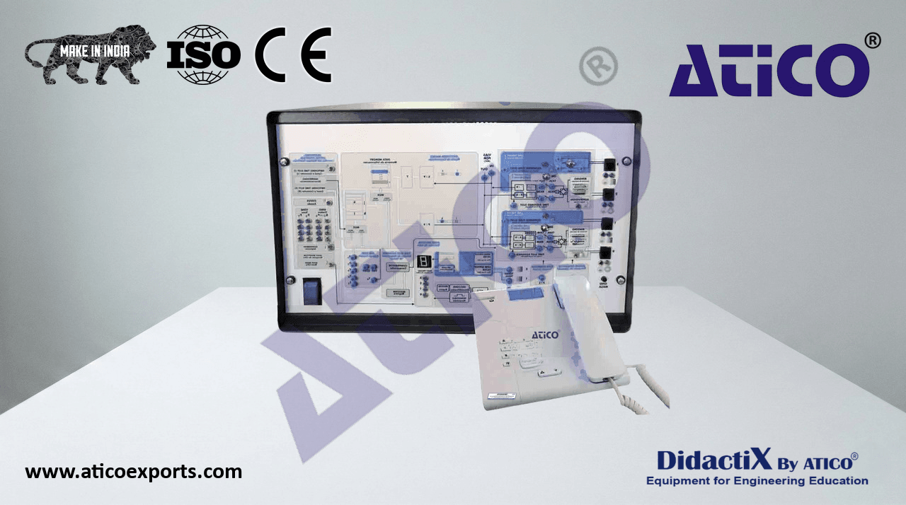
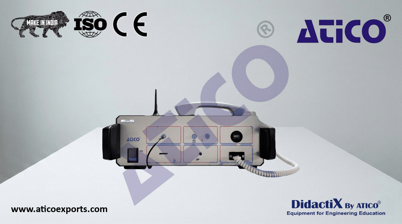
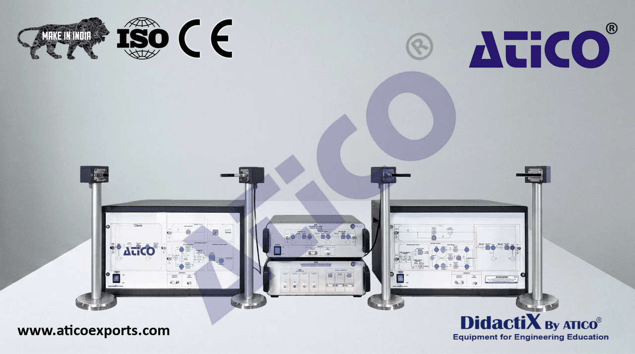
ATENG 10964 — Computer Controlled Microwave Unit
(for main items)
- With this unit there are several options and possibilities:
- Main items: 1, 2, 3, 4 and 5.
- Optional items: 6, 7 and 8.
- Let us describe first the main items (1 to 5):
- 1 ATENG 10964. Unit:
- Power meter:
- Based on thermistor. Wide frequency range: 10 – 12000 MHz.
- Typically level range: -55 dBm – 18 dBm. Stability over temperature.
- Slope: -25 mV/dB.
Connector to interface box.
- Slotted line:
Tunnel diode detector mounted. Frequency
- range: 2 – 18 GHz. VSWR max: 3.5:1.
- Maximum input power: 100 mW (20 dBm). Work in
the quadratic detection zone.
Designed for 8.2 – 12.4 GHz (X-band). Longitudinal
movable diode detector holder.
Millimeter ruler. Waveguide in the standard size
WR-90.
SMA connector to Interface box.
- Gunn oscillator (microwave signal generator):
- Gunn oscillator diode. Frequency band: X band (fixed
at 10.525 GHz).
- Power output: 17 dBm. Waveguide in the standard
- size WR-90. Unit: ATENG 10964
Connector to interface box.
- Broad-wall waveguide directional coupler:
Designed for 8.2 – 12.4 GHz (X-band). Three ports (input, output and coupled).
Waveguide in the standard size WR-90.
- Cross-guide waveguide directional coupler:
Designed for 8.2 – 12.4 GHz (X-band). Four ports (input, output, isolated and coupled). Waveguide
in the standard size WR-90.
- Hybrid Tee:
Designed for 8.2 – 12.4 GHz (X-band).
3 dB coupler. Four ports (2 co-linear, sum and difference). Waveguide in the standard size WR-90.
- 6 dB fixed attenuator:
Designed for 8.2 – 12.4 GHz (X-band). Fixed attenuator at 6 dB. Waveguide in the standard size
WR-90.
- 15 dB fixed attenuator:
Designed for 8.2 – 12.4 GHz (X-band). Fixed attenuator at 15 dB. Waveguide in the standard size
WR-90.
- Vertical variable attenuator:
Designed for 8.2 – 12.4 GHz (X-band). Precision micrometer. Waveguide in the standard size WR-90.
- Horizontal variable attenuator:
Designed for 8.2 – 12.4 GHz (X-band). Precision micrometer. Waveguide in the standard size WR-90.
- Termination load (Dummy load):
Designed for 8.2 – 12.4 GHz (X-band). Adapted load. Waveguide in the standard size WR-90.
Two short circuit terminations.
- Two horn antennas:
Designed for 8.2 – 12.4 GHz (X-band). Sectorial horn flared in the direction of the electric plane
(H-plane).
Waveguide in the standard size WR-90.
- Adjustable termination:
Designed for 8.2 – 12.4 GHz (X-band). Movable short circuit. Precision micrometer. Waveguide in
the standard size WR-90.
- Microwave Absorber Plate: plate with resistive material.
- Microwave Reflector Plate: plate with metallic material.
- Four tower antennas with adjustable height, including each one: waveguide holder and degree disc with
position indicator.
Ten quick release fasteners for an easy operation with the waveguide devices.
3
Complete Technical Specifications (for main items)
- The complete unit includes as well:
Advanced Real-Time SCADA.
Open Control + Multicontrol + Real-Time Control.
Specialized Control Software based on LabVIEW.
Projector and/or electronic whiteboard compatibility allows the unit to be explained and
demonstrated to an entire class at one time.
Capable of doing applied research, real industrial simulation, training courses, etc.
Remote operation and control by the user and remote control for technical support,
are always included.
Totally safe, utilizing 4 safety systems (Mechanical, Electrical, Electronic & Software).
Designed and manufactured under several quality standards.
Optional ICAI software to create, edit and carry out practical exercises, tests, exams,
calculations, etc. Apart from monitoring user's knowledge and progress reached.
This unit has been designed for future expansion and integration. A common expansion is
the Scada-Net (ESN) System which enables multiple students to simultaneously
operate many units in a network.
- EMIC/CIB. Control Interface Box:
The Control Interface Box is part of the computerized system.
SCSI cable to connect the control interface box and the computer.
The unit components are permanently computer controlled, without necessity of changes
or connections during the whole test procedure.
Simultaneous visualization in the computer of all measurement of the system as
received signal power value and slotted line SWR measurement and perform of different
calculations as SWR value, signal frequency, etc.
Graphic representation in real time of the system measurements.
EMIC/CIB
Shield and filtered signals to avoid external interferences.
Safety levels, one mechanical in the unit, another electronic in the control interface and the third one in
the control software.
All measurements are displayed on only one screen in the computer.
Variable attenuators calibration graph, SWR waveform representation and Radiation pattern
representation. Storage of all the analysis data and results in a file.
- 3 EMIC/CCSOF. Computer Control + Data Acquisition + Data Management Software:
Compatible with actual Windows operating systems.
- The software allows to perform different calculations and data registration:
- SWR calculation: the software allows to record the SWR performed by different termination
loads and calculates the SWR value, the distance between minimum and maximum points,
etc.
- Power meter measurement: the software allows to record the power meter value in order
to measure the real attenuation of the fixed attenuators, draw the attenuation depending of
the position of the variable attenuators, study the different couplers, etc.
- Antenna radiation pattern: the software also allows to draw the antenna radiation pattern
with the measurement from the power meter.
Registration and visualization of the power meter and detector diode of the slotted line in an
automatic and simultaneous way.
Flexible, open and multicontrol software, developed with actual windows graphic systems,
acting simultaneously on all measurement values.
Management, processing, comparison and storage of data. EMIC/CCSOF
This unit allows the 30 students of the classroom to visualize simultaneously all the results
and the manipulation of the unit, during the process, by using a projector or an electronic
whiteboard.
4 Cables and Accessories, for normal operation.
- 5Manuals:
- This unit is supplied with 8 manuals: Required Services, Assembly and Installation, Interface and
Control Software, Starting-up, Safety, Maintenance, Calibration & Practices Manuals.
- References 1 to 5 are the main items: ATENG 10964 + EMIC/CIB + EMIC/CCSOF + Cables and Accessories + Manuals are included in the
minimum supply for enabling normal and full operation.
4