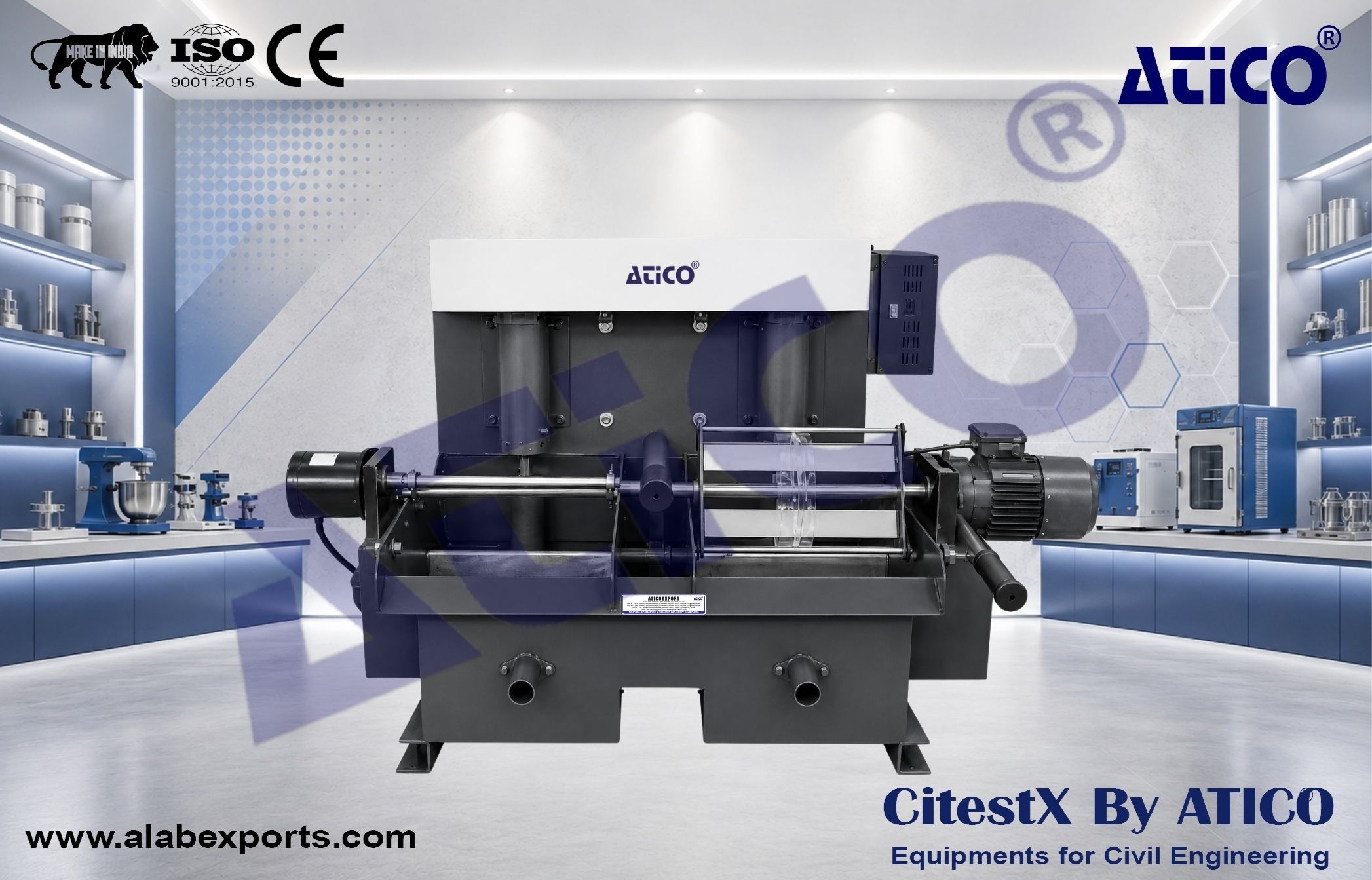
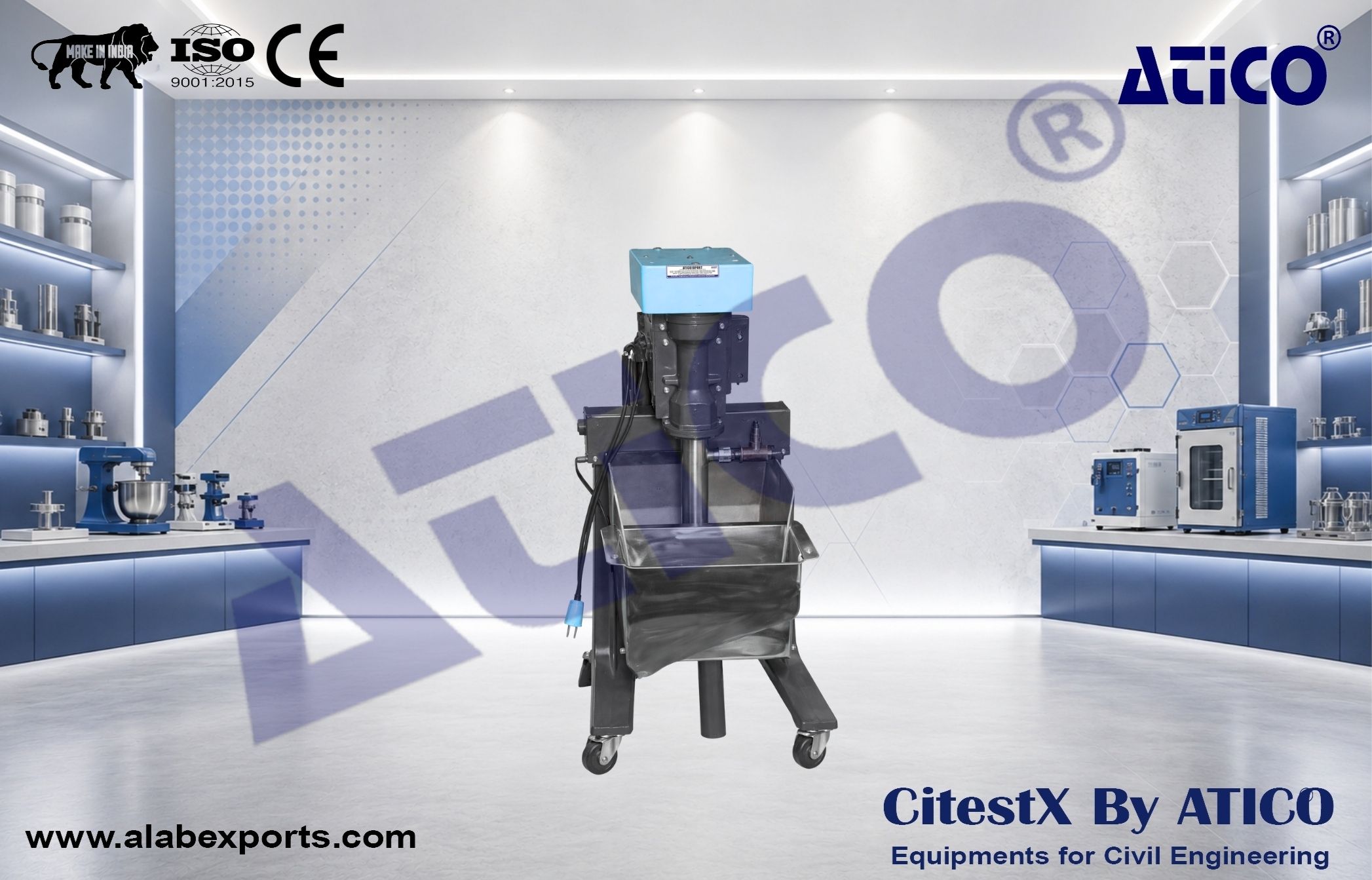
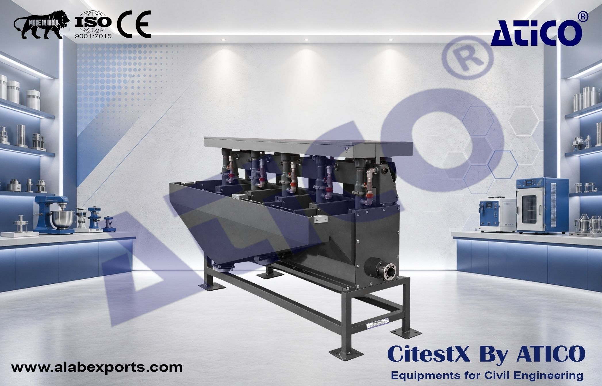
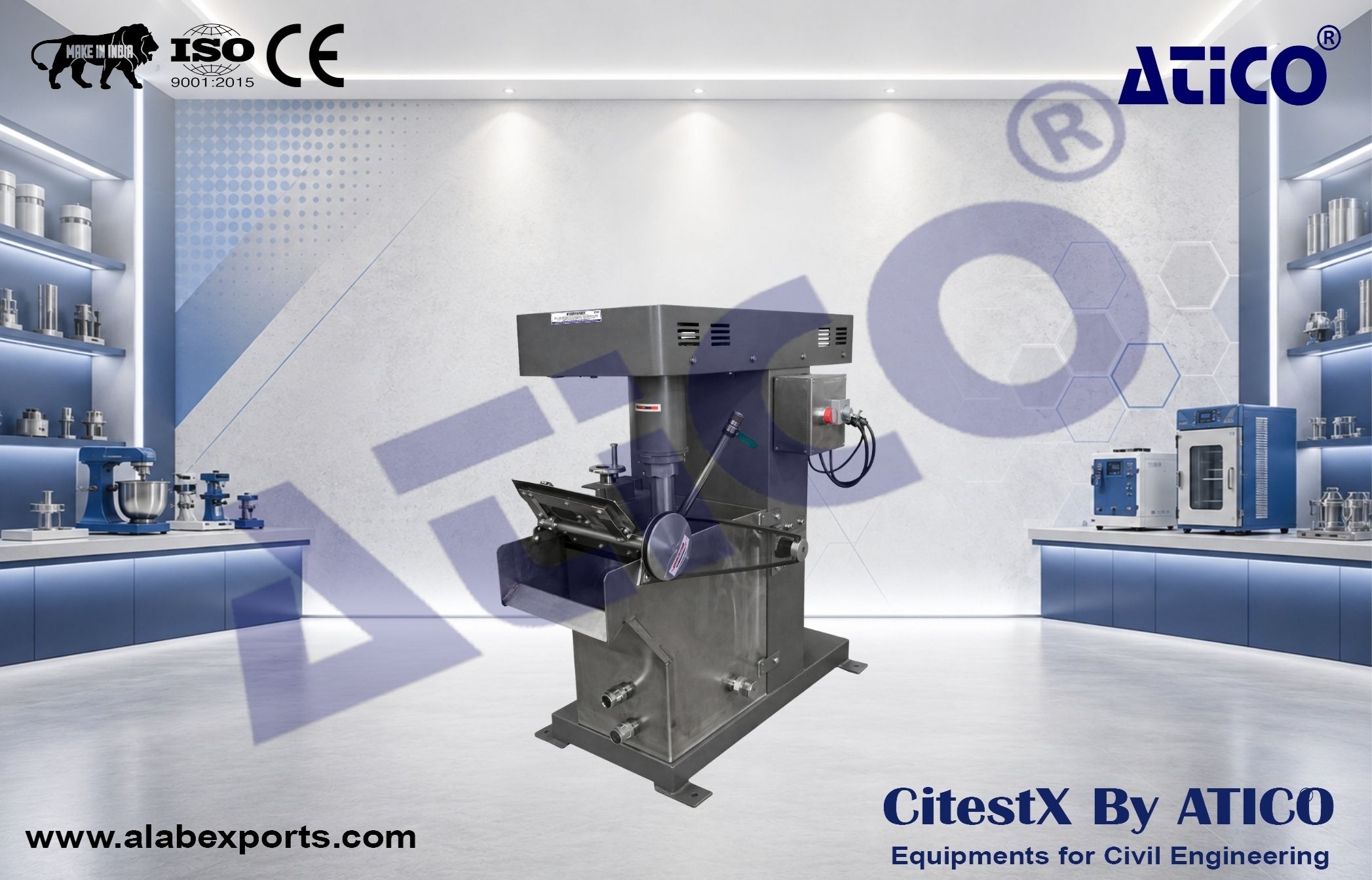
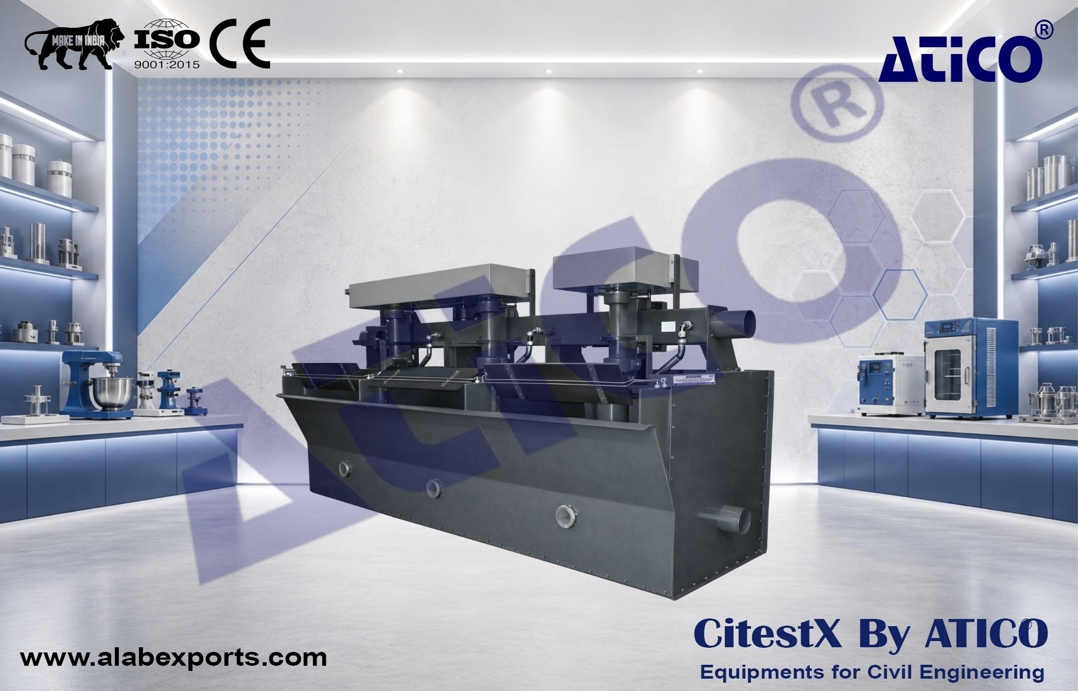
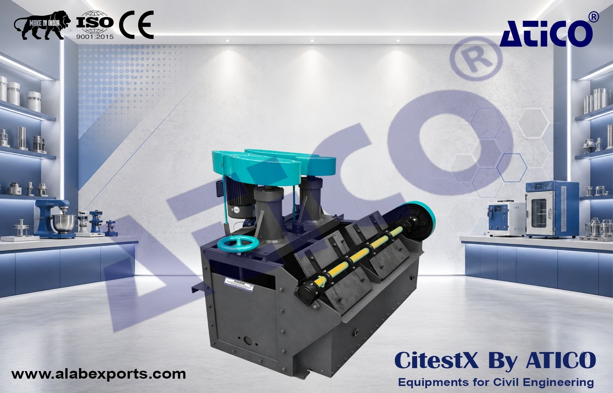
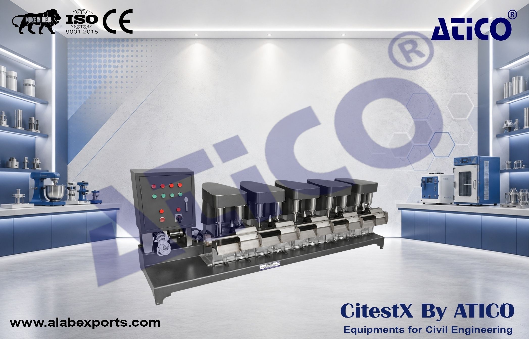
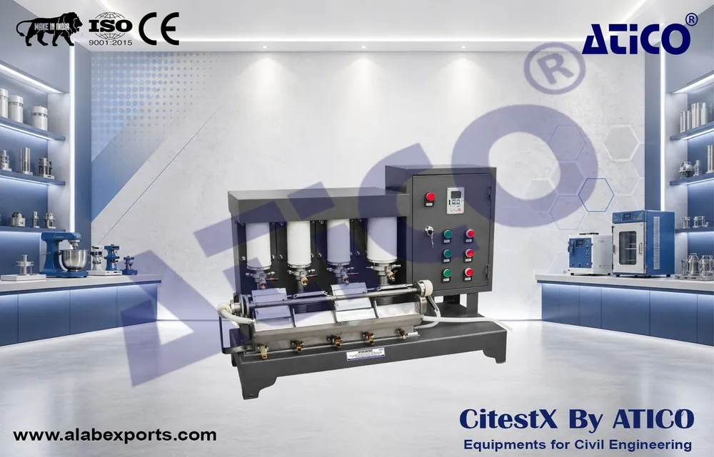
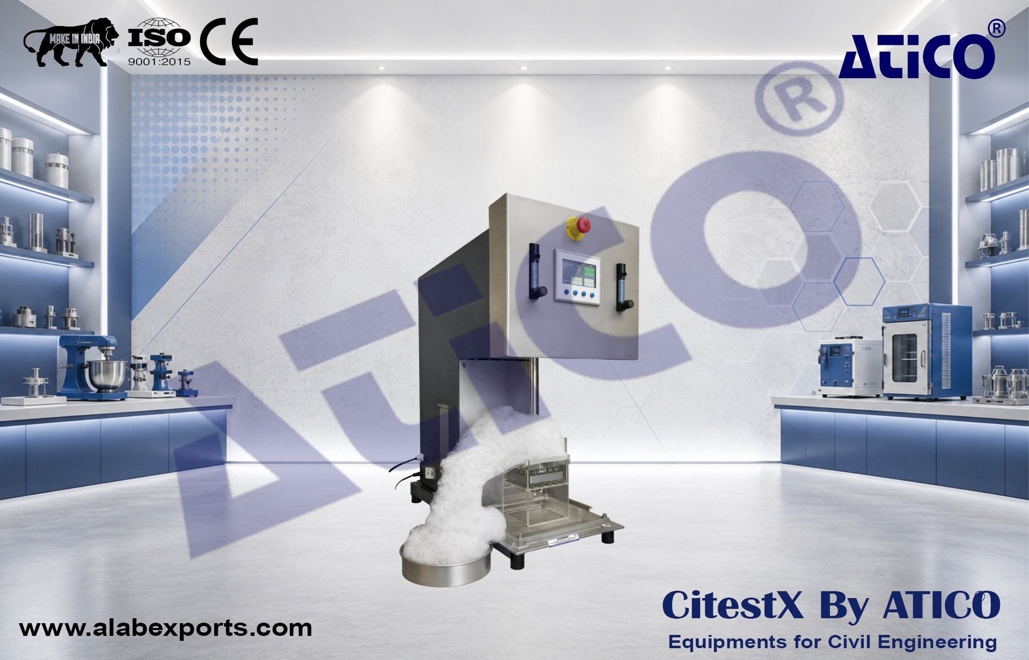
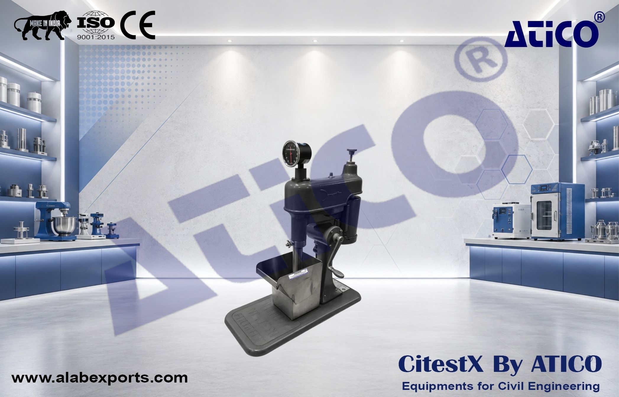
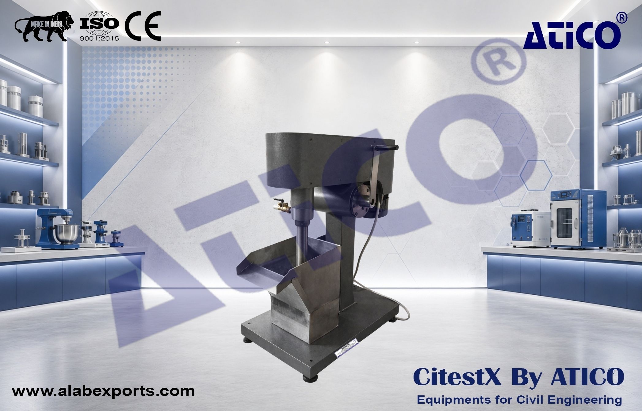
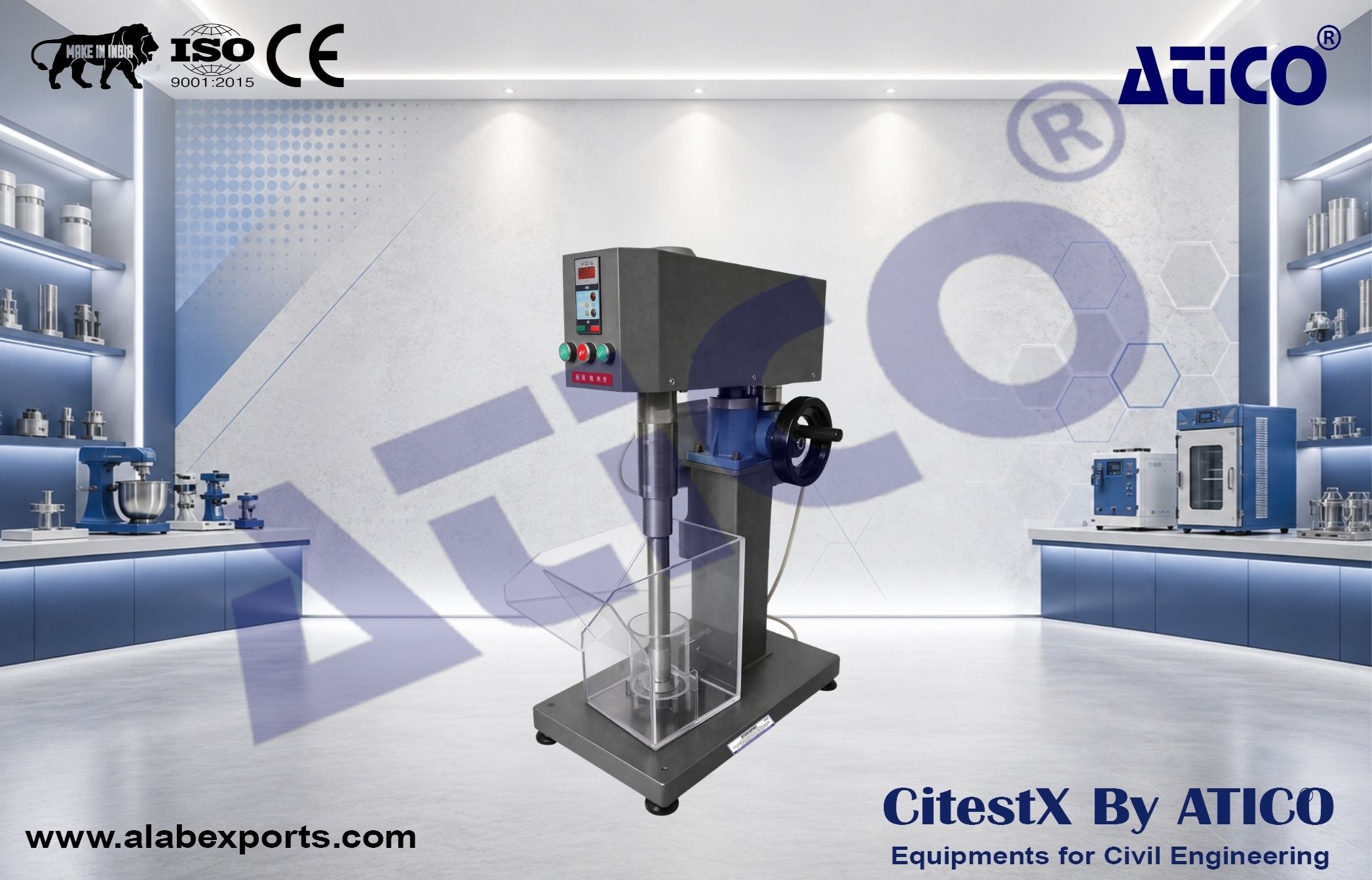
Small plant or pilot plant flotation cells designed as twin-cell banks using a self-aspirated mechanical flotation system. These units are constructed from stainless steel and can be arranged in series to form complete flotation circuits for small-scale processing.
Operational / Working Principle
- Slurry flows from feed cell through intermediate and tail cells
- Air is self-aspirated through vertical pipe by rotating impeller
- Impeller mixes slurry and air for flotation
- Froth forms at the top and is removed by scraper
- Tailings are discharged from the final cell
Design Components
- Impeller System:
- Disk-type impeller with radial blades
- Mounted on vertical shaft
Air System :
- Air drawn through vertical pipe
- Controlled by gap (max 3 mm) between impeller and safety disk
Flow System :
- Overflow and discharge channels
- Internal slurry circulation between cells
Froth Removal :
- Rotary scraper mechanism
- Driven by belt and reducer system
Installation / Operation Notes
- Select number of cells based on required capacity (KPH/TPD)
- Ideal configuration: 2 to 8 cells per circuit
- Adjust slurry level and froth thickness using control plates
- Maintain proper V-belt tension
- Ensure correct alignment and clearance in impeller system
Maintenance Notes
- Replace lining plates when worn
- Maintain impeller-to-disk clearance (max 3 mm)
- Check and adjust belt tension regularly
- Ensure proper lubrication of bearings