ATENG 11435 — Computer Controlled Diesel Engine Electrical Generator Application
(for main items)
- With this unit there are several options and possibilities:
- Main items: 1, 2, 3, 4 and 5.
- Optional items: 6, 7 and 8.
- Let us describe first the main items (1 to 5):
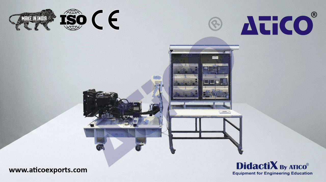
- 1 TDEGC/50 or TDEGC/60 Unit:
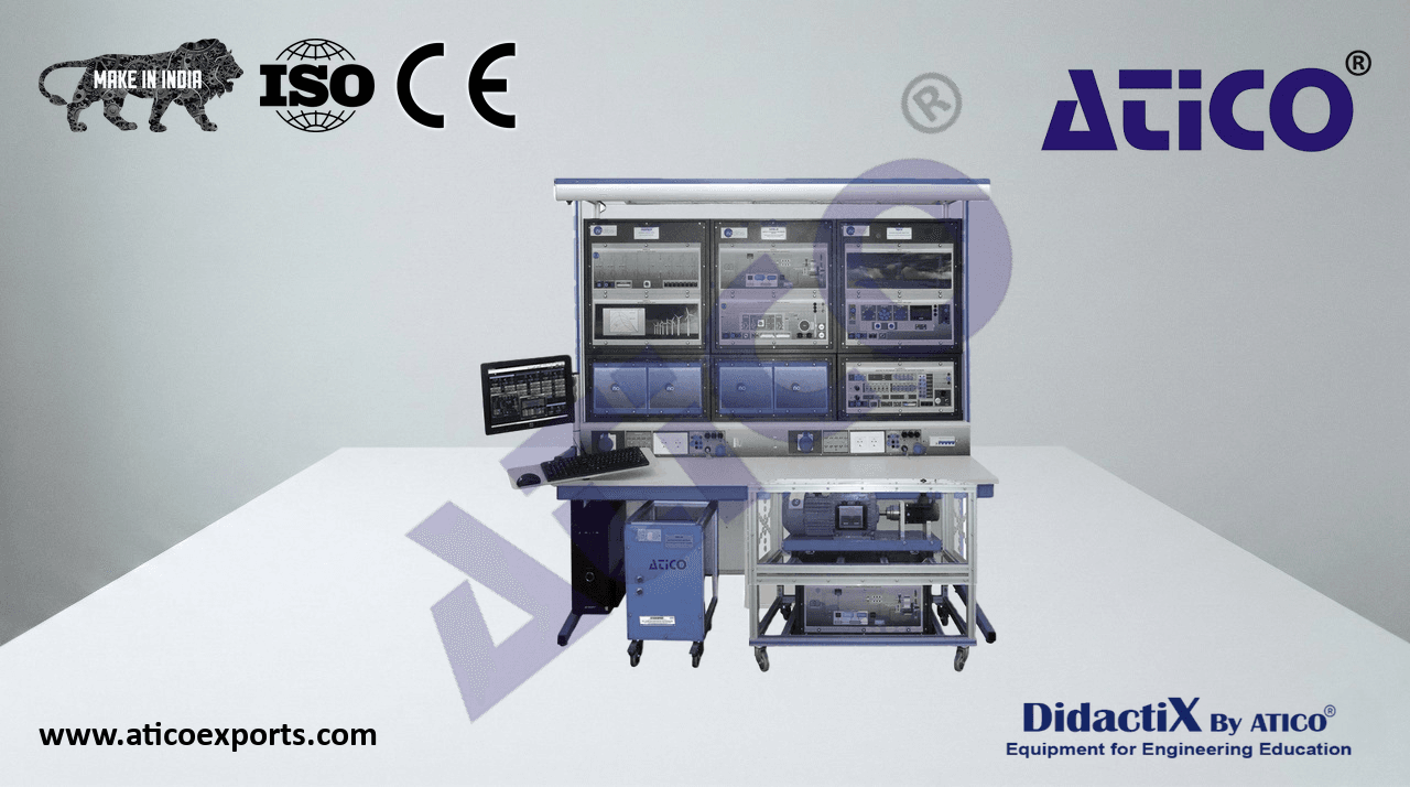
AEL-WBMP. Electrical Workbench (Mobile Small).
- Control and Supervision Panel:
Enables to connect up to 16 diesel generators in parallel-island with
distribution of active and reactive load and start/stop in function of the load
demand.
Includes analogical outputs to control voltage and frequency regulators.
Three-phase measurements of the grid and generator voltage.
Three-phase measurements of the generator current and power.
Single-phase measurement of the grid current.
Sensor “island grid/parallel grid”.
Digital signal “local/remote control”.
- Alarm indicators: over/undervoltage, reverse power, overcurrent, over/
underfrequency, shutdown alarms and low level fuel.
- Remote control signal states indicators: ready for operation, start request, GCB
synchronization conditions, remote closing signal for GCB synchronization,
mains parallel operation, isolated operation, emergency stop.
- Maintenance panel: key of permission for maintenance, ignition switch,
starter signal.
- Back-Up protections: earth leakage relay, three-phase overcurrent relay.
- Generator protections: max/mín-voltage (59/27), max/min-frequency
(81O/U), dead bus detection, reverse power/reduce (32R/F), overcurrent
time defined curve (50/51), inverse time overcurrent (IEC255).
- Motor: over/sub speed (12).
PID Power Factor Control.
PID Excitation Control.
PID Active Power Control. AEL-WBMP. Electrical Workbench (Mobile
- PID Speed Control. Small) including:
- Control and Supervision Panel.
- Instrumentation Panel:
- Instrumentation Panel.
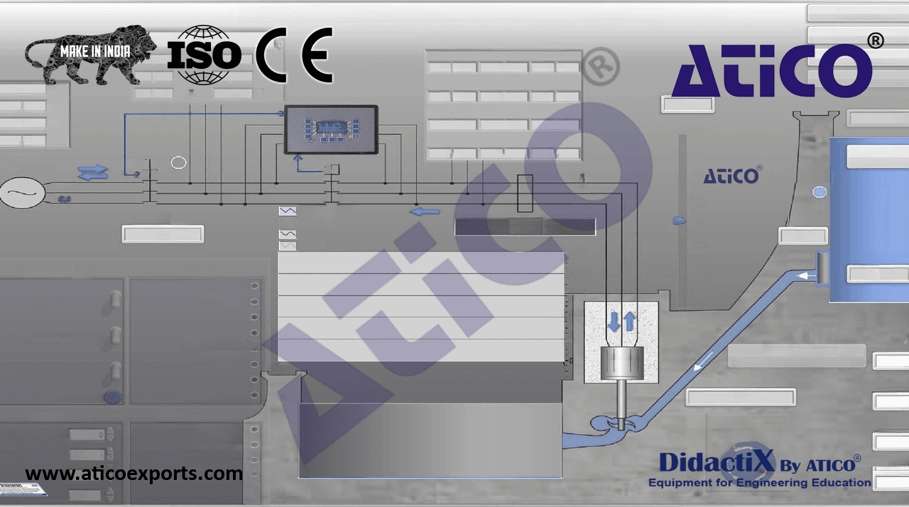
- DC Power Analyzer: - Connection Diagram and SCADA Panel.
- Rated voltage range: 0 –100 VDC. - Three-Phase Resistive Industrial Panel.
- Rated current range: 0 – 10 A. - Three-Phase Inductive Industrial Panel.
- Three-Phase Capacitive Industrial Panel.
Communication port RS-485.
- DC Analog Ammeter:
- Rated current range: 0 – 2.5A.
- AC Generator Power Analyzer:
- Display for instantaneous variables: 3 x 3 digits.
- Display for energies: 8 + 1 digits.
- Voltage:
- VL-N = 185 V to 460 V.
- VL-L = 320 V to 800 V.
- Current:
- Phase current: 0.03 to 10 A.
- Neutral current: 0.09 to 10 A.
- AC Mains Power Analyzer:
- Display for instantaneous variables: 3 x 3 digits.
- Display for energies: 8 + 1digits.
- Voltage:
- VL-N = 185 V to 460 V.
- VL-L = 320 V to 800 V.
- Current:
- Phase current: 0.03 to 10 A.
- Neutral current: 0.09 to 10 A.
- Frequency: 48 to 62 Hz 0.1 Hz.
- Power: active, reactive and apparent.
- Power factor: power factor for resistive, inductive and capacitive load types.
5
Complete Technical Specifications (for main items)
- Connection Diagram and SCADA Panel:
Panel with real diagram.
Emergency stop push-button.
- Three voltage indicators for three bus bar parts: generation indicator lamp, loads indicator lamp and mains indicator lamp.
Three synchronization lamps indicator.
GCB (generator circuit breaker) and MCB (mains circuit breaker) circuit breaker lamps.
P1 power connector for diesel engine-generator.
MAINS connector for synchronization operation.
USB 1 communication connector for maintenance operations.
ON / OFF switch.
- 230 VAC Power supply cable with single-phase plug.
- 230 VAC, 30mA differential protection.
- Three-Phase Resistive Industrial Panel:
- Three 1 kW three-phase resistor loads 3 x (3 x 150) ohms.
Three manual commutators to change the resistive load.
Three load indicator lamps.
- Three-Phase Inductive Industrial Panel:
Three 1 kVar three-phase inductive loads
Three manual commutators to change the inductive load.
Three load indicator lamps.
- Three-Phase Capacitive Industrial Panel:
Three 1 kVar three-phase capacitive loads.
Three manual commutators to change the capacitive load.
Three load indicator lamps.
- Diesel Engine Generator Group:
- Diesel Engine:
(The Diesel Engine may change at any moment, providing the same or better
features than those required for the unit).
Four stroke diesel engine with cylinders in line.
Liquid cooled with axial fan.
Forced lubrication with vane pump on the crankshaft.
Water pump in the engine block.
- Cylinder: 3.
- Engine displ (cm3): 1028.
- Injection system: indirect (IDI).
- Compression ratio: 22.8:1.
- Nominal power (kW / HP): 20 kW / 26,8 HP.
- Max torque (Nm/rpm): 67.0 / 2000.
Diesel fuel.
- Oil sump capacity (l): 2.4.
- Phisical characteristics:
- Dimensions: 519 x 516 x 412 mm.
- Dry weight: 85 Kg.
Diesel Engine Generator Group
Air filter.
- Fuel tank: 160 l.
- Synchronous generator:
- Synchronous speed: 1500 rpm.
- Nominal frequency: 50 Hz or 60 Hz (according to requested reference).
- Apparent power: 8 kVA.
- Nominal voltage: 400 VAC.
- Nominal current: 11 A
- Power factor: 0.8.
- Number of poles: 4.
- Nominal current excitation: 1.5 A.
- Nominal voltage excitation: 23.7 A.
6
Complete Technical Specifications (for main items)
- The complete unit includes as well:
Real and complete control of a diesel engine synchronous generator.
Automatic control over the engine speed and synchronous generator current excitation.
Diesel engine synchronous generator synchronization operations studies.
Diesel engine synchronous generator stand-alone operations studies.
Diesel engine-generator stability in stand-alone and parallel operations studies.
Studies of diesel engine synchronous generator in micro-grids, ships, black-out situations.
Analysis of engine PID speed control signal.
Analysis of synchronous generator PID excitation control signal.
Analysis of engine PID active power control signal.
Analysis of engine-synchronous generator PID power factor control signal.
Advanced Real-Time SCADA and PID Control.
Open Control + Multicontrol + Real-Time Control.
Specialized Control Software based on Labview.
National Instruments Data Acquisition board (250 KS/s, kilo samples per second).
Projector and/or electronic whiteboard compatibility allows the unit to be explained and
demonstrated to an entire class at one time.
Capable of doing applied research, real industrial simulation, training courses, etc.
Remote operation and control by the user and remote control for technical support
are always included.
Totally safe, utilizing 4 safety systems (Mechanical, Electrical, Electronic & Software).
Designed and manufactured under several quality standards.
This unit has been designed for future expansion and integration. A common expansion is
the Scada-Net (ESN) System which enables multiple students to simultaneously
operate many units in a network.
- 2 DAB. Data Acquisition Board:
The Data Acquisition board is part of the SCADA system.
PCI Express Data acquisition board (National Instruments) to be placed in a computer slot. Bus
PCI Express.
- Analog input:
Number of channels= 16 single-ended or 8 differential. Resolution=16 bits, 1 in 65536.
- Sampling rate up to: 250 KS/s (kilo samples per second).
- Input range (V)=±10 V. Data transfers=DMA, interrupts, programmed I/0. DMA channels=6.
DAB
- Analog output:
Number of channels=2. Resolution=16 bits, 1 in 65536.
- Maximum output rate up to: 900 KS/s.
- Output range (V)=±10 V. Data transfers=DMA, interrupts, programmed I/0.
- Digital Input/Output:
- Number of channels=24 inputs/outputs. D0 or DI Sample Clock frequency: 0 to 100 MHz.
- Timing: Number of Counter/timers=4. Resolution: Counter/timers: 32 bits.
The Data Acquisition board model may change at any moment, providing the same or better
features than those required for the unit.
7
Complete Technical Specifications (for main items)
3 TDEGC/CCSOF. PID Computer Control + Data Acquisition + Data Management
- Software:
The three softwares are part of the SCADA system.
Compatible with actual Windows operating systems. Graphic and intuitive simulation of the
process in screen. Compatible with the industry standards.
Registration and visualization of all process variables in an automatic and simultaneous way.
Flexible, open and multicontrol software, developed with actual windows graphic systems,
acting simultaneously on all process parameters.
Analog and digital PID control.
PID menu and set point selection required in the whole work range.
Management, processing, comparison and storage of data.
Sampling velocity up to 250 KS/s (kilo samples per second).
Calibration system for the sensors involved in the process. TDEGC/CCSOF
It allows the registration of the alarms state and the graphic representation in real time.
Comparative analysis of the obtained data, after the process and modification of the conditions during
the process.
Open software, allowing the teacher to modify texts, instructions. Teacher’s and student’s
passwords to facilitate the teacher’s control on the student, and allowing the access to different work
levels.
This unit allows the 30 students of the classroom to visualize simultaneously all the results
and the manipulation of the unit, during the process, by using a projector or an electronic
whiteboard.
4 Cables and Accessories, for normal operation.
- 5Manuals:
- This unit is supplied with 8 manuals: Required services, Assembly and Installation, Control software,
Starting-up, Safety, Maintenance, Calibration & Practices manuals.
- References 1 to 5 are the main items: TDEGC/50 or TDEGC/60 Unit + DAB + TDEGC/CCSOF + Cables and Accessories + Manuals
are included in the minimum supply for enabling normal and full operation.
8