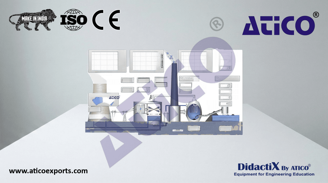
ATENG 11575 — Computer Controlled Steam Turbine
(for main items)
- With this unit there are several options and possibilities:
- Main items: 1, 2, 3, 4, 5 and 6.
- Optional items: 7, 8 and 9.
- Let us describe first the main items (1 to 6):
- 1 ATENG 11575. Unit:
Bench-top unit.
Anodized aluminum frame and panels made of painted steel.
Main metallic elements made of stainless steel.
Diagram in the front panel with distribution of the elements
similar to the real one.
- The unit includes:
- Steam turbine:
Single stage axial flow impulse steam turbine mounted on
a vertical shaft.
- Diameter: 82 mm.
- Angle of incidence of the injector: 20 º.
- Number of blades: 30.
- Max. speed: 20000 rpm.
- Max. power: 15 W.
- Brake:
Friction by means of a belt.
- Effective radius: 25 mm.
- Condenser:
Vertical glass chamber.
Includes a coil through which the cold water circulates.
Two computer controlled solenoid valves, situated in the steam
inlet line and mounted in series for system security.
- Computer controlled solenoid valve to evacuate the Unit: ATENG 11575
condensed steam in the condenser.
Three regulation valves to regulate the steam inlet, the condensed outlet and the refrigeration water.
- Instrumentation:
- Two pressure sensors: one sensor situated in the steam inlet line, range: 0 – 10 bar and other
- sensor situated in the upper side of the condenser, range: -1 – 1.6 bar.
- Force sensor (load cell) to measure the force of the brake, range: 0 – 20 N.
- Speed sensor to measure the speed of the turbine shaft, range: 0 – 20000 rpm.
- Flow sensor to measure the refrigeration water flow, range: 0.25 – 6.5 l/min.
Level sensor to measure the condensed steam volume in the condenser.
Five “J” type temperature sensors. They are situated in the steam inlet line, in the upper and lower
side of the condenser and in the condensation water inlet and outlet lines.
The instrumentation allows to measure the braking torque, turbine power, steam mass flow and
specific heat (kg required to obtain a kW).
- The unit is equipped with safety devices: a pressure switch, a safety valve for the condenser and
PMMA protection screens.
- The complete unit includes as well:
Advanced Real-Time SCADA.
Open Control + Multicontrol + Real-Time Control.
Specialized Control Software based on LabVIEW.
National Instruments Data Acquisition board (250 KS/s, kilo samples per second).
Calibration exercises, which are included, teach the user how to calibrate a sensor and the
importance of checking the accuracy of the sensors before taking measurements.
Projector and/or electronic whiteboard compatibility allows the unit to be explained and
demonstrated to an entire class at one time.
Capable of doing applied research, real industrial simulation, training courses, etc.
Remote operation and control by the user, as well as remote support from technical
support, are always included.
Totally safe, utilizing 4 safety systems (Mechanical, Electrical, Electronic & Software).
Designed and manufactured under several quality standards.
Optional ICAI software to create, edit and carry out practical exercises, tests, exams,
calculations, etc. Apart from monitoring user's knowledge and progress reached.
This unit has been designed for future expansion and integration. A common expansion is
the Scada-Net (ESN) System which enables multiple students to simultaneously
operate many units in a network.
- Required elements (Not included):
- ATENG 12019. Steam Generator (6 kW) (for high pressures and high temperatures).
4
Complete Technical Specifications (for main items)
- TTVC/CIB. Control Interface Box:
The Control Interface Box is part of the SCADA system.
Control interface box with process diagram in the front panel and with the same distribution that
the different elements located in the unit, for an easy understanding by the student.
- All sensors, with their respective signals, are properly manipulated from -10V. to +10V. computer output.
Sensors connectors in the interface have different pines numbers (from 2 to 16), to avoid
connection errors.
Single cable between the control interface box and computer.
The unit control elements are permanently computer controlled, without necessity of
changes or connections during the whole process test procedure.
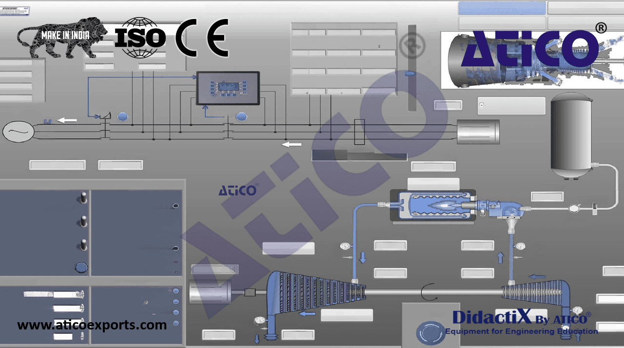
Simultaneous visualization in the computer of all parameters involved in the process.
Calibration of all sensors involved in the process.
Real time curves representation about system responses.
Storage of all the process data and results in a file.
Graphic representation, in real time, of all the process/system responses.
All the actuators’ values can be changed at any time from the keyboard allowing the
analysis about curves and responses of the whole process.
All the actuators and sensors values and their responses are displayed on only one screen in the
computer.
Shield and filtered signals to avoid external interferences.
Real time computer control with flexibility of modifications from the computer keyboard
of the parameters, at any moment during the process. TTVC/CIB
Real time computer control for pumps, compressors, heating elements, control valves, etc.
Real time computer control for parameters involved in the process simultaneously.
Open control allowing modifications, at any moment and in real time, of parameters involved in the
process simultaneously.
Three safety levels, one mechanical in the unit, another electronic in the control interface and
the third one in the control software.
- 3 DAB. Data Acquisition Board:
The Data Acquisition board is part of the SCADA system.
PCI Express Data acquisition board (National Instruments) to be placed in a computer slot. Bus
PCI Express.
- Analog input:
Number of channels= 16 single-ended or 8 differential. Resolution=16 bits, 1 in 65536.
- Sampling rate up to: 250 KS/s (kilo samples per second).
- Input range (V)=±10 V. Data transfers=DMA, interrupts, programmed I/0. DMA channels=6.
- Analog output:
Number of channels=2. Resolution=16 bits, 1 in 65536.
- Maximum output rate up to: 900 KS/s.
- Output range (V)=±10 V. Data transfers=DMA, interrupts, programmed I/0. DAB
- Digital Input/Output:
- Number of channels=24 inputs/outputs. D0 or DI Sample Clock frequency: 0 to 100 MHz.
- Timing: Number of Counter/timers=4. Resolution: Counter/timers: 32 bits.
The Data Acquisition board model may change at any moment, providing the same or better
features than those required for the unit.
- 4 TTVC/CCSOF. Computer Control + Data Acquisition + Data Management Software:
The three softwares are part of the SCADA system.
Compatible with actual Windows operating systems. Graphic and intuitive simulation of the process in
screen. Compatible with the industry standards.
Registration and visualization of all process variables in an automatic and simultaneous way.
Flexible, open and multicontrol software, developed with actual windows graphic systems,
acting simultaneously on all process parameters.
Management, processing, comparison and storage of data.
Sampling velocity up to 250 KS/s (kilo samples per second).
Calibration system for the sensors involved in the process.
It allows the registration of the alarms state and the graphic representation in real time.
Comparative analysis of the obtained data, after the process and modification of the conditions
during the process.
Open software, allowing the teacher to modify texts, instructions. Teacher’s and
student’s passwords to facilitate the teacher’s control on the student, and allowing the access
to different work levels.
TTVC/CCSOF
This unit allows the 30 students of the classroom to visualize simultaneously all the results
and the manipulation of the unit, during the process, by using a projector or an electronic
whiteboard.
5 Cables and Accessories, for normal operation.
- 6Manuals:
- This unit is supplied with 8 manuals: Required services, Assembly and Installation, Interface and
Control software, Starting-up, Safety, Maintenance, Calibration & Practices manuals.
- References 1 to 6 are the main items: ATENG 11575 + TTVC/CIB + DAB + TTVC/CCSOF + Cables and Accessories + Manuals are included in
the minimum supply for enabling normal and full operation.
5