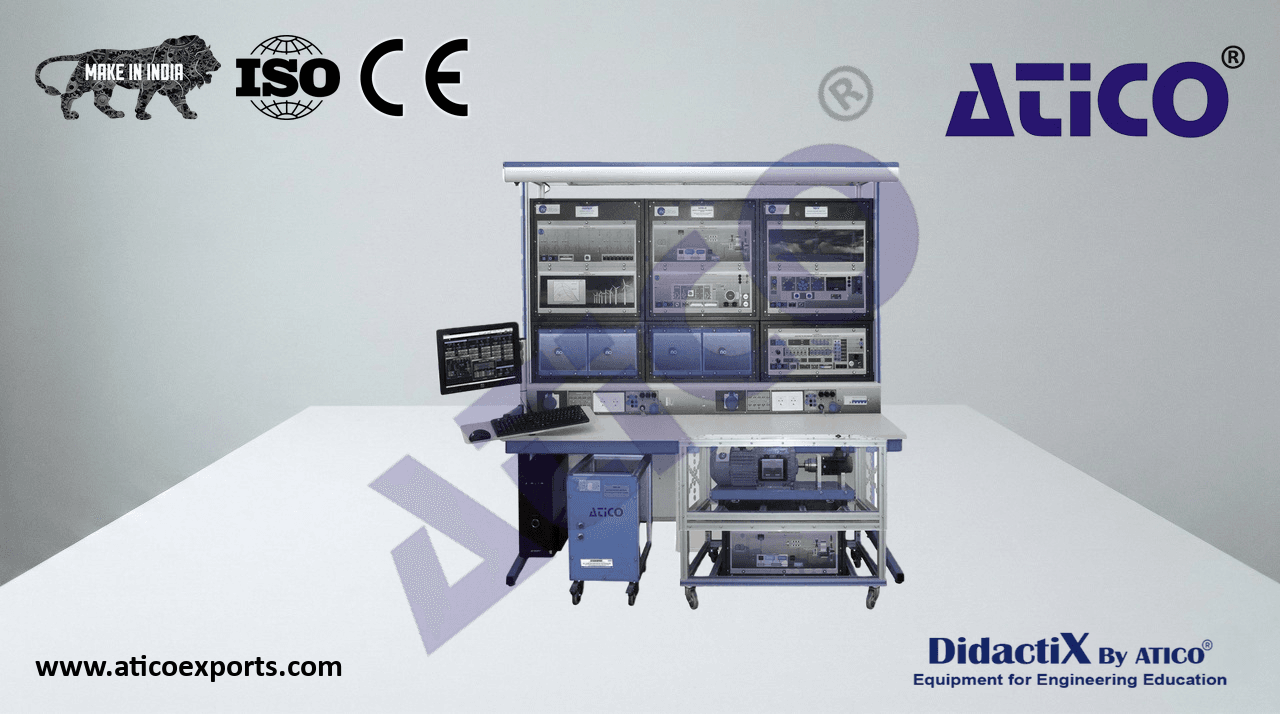
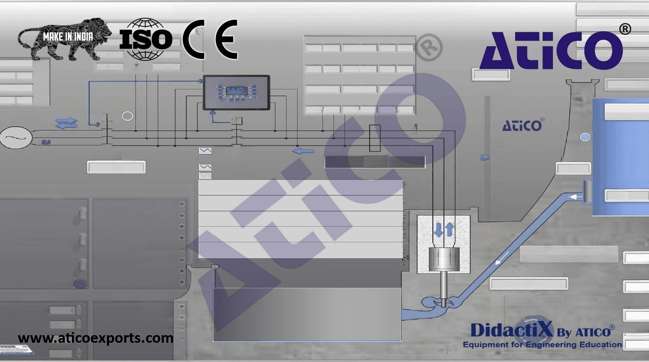
ATENG 11525 — Computer Controlled Waves Energy Unit
(for main items)
- With this unit there are several options and possibilities:
- Main items: 1, 2, 3, 4, 5 and 6.
- Optional items: 7, 8, 9, 10 and 11.
- Let us describe first the main items (1 to 6):
- 1EOMC-UB. Base Service Unit and Waves Generator:
Anodized aluminum frame and panels made of painted steel.
Main metallic elements made of stainless steel.
Diagram in the front panel with distribution of the elements similar to the real one.
- The “EOMC-UB” unit mainly consists of:
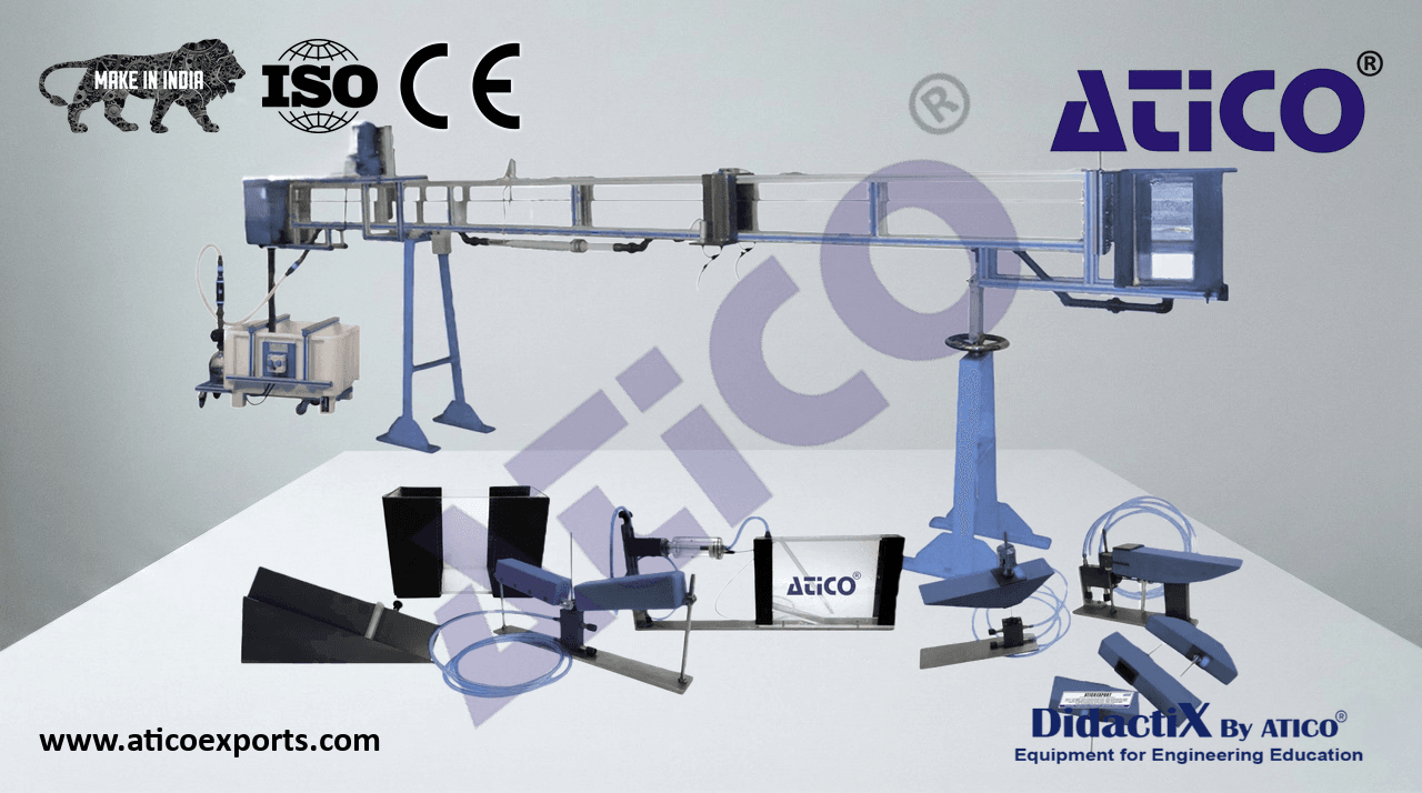
- CF80/5. Flow Channel (section: 80 x 300 mm), length: 5 m.
Channel of rectangular section with transparent walls. It
is assembled on supports, with a system to control the
- inclination of the channel. Channel slope: adjustable.
- Section: 80 x 300 mm.
- Length: 5 m.
- Inlet tank (capacity: 38 l), with flow stilling and drain
valve.
- Reception tank (capacity: 38 l), with drain valve.
- Elevation angle: each cm in the scale corresponds to
0.18°, the maximum elevation angle is 3°.
Flow control valve.
Pipes.
- Storage tank:
- Capacity: 140 l, approx.
- Impulsion pump, computer controlled:
- Power: 0.37 kW. Max. flow: 80 l/min.
- Max. pressure: 20.1 m. Unit: ATENG 11525
ON / OFF safety switch.
- Manometric panel:
- Formed by two PMMA pipes of 1000 mm of length mounted on an aluminum frame.
- Orifice plate:
- Material: PVC. Inner diameter: 80 mm.
- Venturi tube:
- Material: PMMA. Length: 180 mm.
- Larger section: 32 mm. Smaller section: 20 mm.
CFGO-K1. Mechanical Wave Generation Elements Kit. To produce different types of waves. The
waves frequency is modified by changing the blade rotating speed from the computer.
Two reservoirs to collect and measure the impelled water flow by the modules (EOMC-1, EOMC-2,
EOMC-3 and EOMC-5).
- Flow sensors:
Sensor for the Base Service Unit and Waves Generator, “EOMC-UB”, to measure the flow at the
- pump outlet, range: 2 – 150 l/min.
Two sensors for the “Energy Generation Modules” to measure the impelled water flow by the
modules. These sensors calculate the flow from the water height in the reservoirs. These water
- heights are measure by two pressure sensors, range: 0 – 300 mm w.c.
Differential pressure sensor for the Base Services Unit and Waves Generator, “EOMC-UB”, to
- measure the pressure drop in the orifice plate and the Venturi tube, range: 0 – 1 psi.
Waves sensor for the Base Service Unit and Waves Generator, “EOMC-UB”. This sensor allows to
measure the frequency and the amplitude of the waves generated by the waves generator.
Speed sensor to measure the blade rotating speed of the waves generator.
- The complete unit includes as well:
Advanced Real-Time SCADA.
Open Control + Multicontrol + Real-Time Control.
Specialized Control Software based on LabVIEW.
National Instruments Data Acquisition board (250 KS/s, kilo samples per second).
Calibration exercises, which are included, teach the user how to calibrate a sensor and the
importance of checking the accuracy of the sensors before taking measurements.
Projector and/or electronic whiteboard compatibility allows the unit to be explained and
demonstrated to an entire class at one time.
Capable of doing applied research, real industrial simulation, training courses, etc.
Remote operation and control by the user, as well as remote support from technical
support, are always included.
Totally safe, utilizing 4 safety systems (Mechanical, Electrical, Electronic & Software).
Designed and manufactured under several quality standards.
Optional ICAI software to create, edit and carry out practical exercises, tests, exams,
calculations, etc. Apart from monitoring user's knowledge and progress reached.
This unit has been designed for future expansion and integration. A common expansion is
the Scada-Net (ESN) System which enables multiple students to simultaneously
operate many units in a network.
- Required elements (at least one) (Not included):
- EOMC-1. Floating Buoy Module.
- EOMC-2. Oscillating Water Column Module.
- EOMC-3. Pelamis Module.
- EOMC-4. Tapered Channel Module.
- EOMC-5. Salter’s Duck Module.
4
Complete Technical Specifications (for main items)
- EOMC/CIB. Control Interface Box:
The Control Interface Box is part of the SCADA system.
Control interface box with process diagram in the front panel and with the same distribution that
the different elements located in the unit, for an easy understanding by the student.
- All sensors, with their respective signals, are properly manipulated from -10V. to +10V. computer
output.
Sensors connectors in the interface have different pines numbers (from 2 to 16), to avoid
connection errors.
Single cable between the control interface box and computer.
The unit control elements are permanently computer controlled, without necessity of
changes or connections during the whole process test procedure.
Simultaneous visualization in the computer of all parameters involved in the process.
Calibration of all sensors involved in the process.
Real time curves representation about system responses.
Storage of all the process data and results in a file.
Graphic representation, in real time, of all the process/system responses.
All the actuators’ values can be changed at any time from the keyboard allowing the
analysis about curves and responses of the whole process.
All the actuators and sensors values and their responses are displayed on only one screen in the
computer. EOMC/CIB
Shield and filtered signals to avoid external interferences.
Real time computer control with flexibility of modifications from the computer keyboard of the
parameters, at any moment during the process.
Real time computer control for pumps, compressors, heating elements, control valves, etc.
Real time computer control for parameters involved in the process simultaneously.
Open control allowing modifications, at any moment and in real time, of parameters involved in the
process simultaneously.
Three safety levels, one mechanical in the unit, another electronic in the control interface and
the third one in the control software.
- 3 DAB. Data Acquisition Board:
The Data Acquisition board is part of the SCADA system.
PCI Express Data acquisition board (National Instruments) to be placed in a computer slot. Bus
PCI Express.
- Analog input:
Number of channels= 16 single-ended or 8 differential. Resolution=16 bits, 1 in 65536.
- Sampling rate up to: 250 KS/s (kilo samples per second).
- Input range (V)=±10 V. Data transfers=DMA, interrupts, programmed I/0. DMA channels=6.
- Analog output:
Number of channels=2. Resolution=16 bits, 1 in 65536.
- Maximum output rate up to: 900 KS/s.
- Output range (V)=±10 V. Data transfers=DMA, interrupts, programmed I/0.
DAB
- Digital Input/Output:
- Number of channels=24 inputs/outputs. D0 or DI Sample Clock frequency: 0 to 100 MHz.
- Timing: Number of Counter/timers=4. Resolution: Counter/timers: 32 bits.
The Data Acquisition board model may change at any moment, providing the same or better
features than those required for the unit.
- 4 EOMC/CCSOF. Computer Control + Data Acquisition + Data Management Software:
The three softwares are part of the SCADA system.
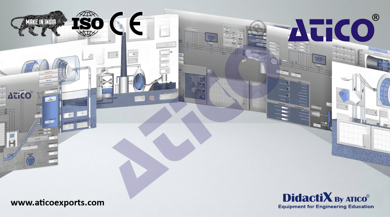
Compatible with actual Windows operating systems. Graphic and intuitive simulation of the
process in screen. Compatible with the industry standards.
Registration and visualization of all process variables in an automatic and simultaneous way.
Flexible, open and multicontrol software, developed with actual windows graphic systems,
acting simultaneously on all process parameters.
Management, processing, comparison and storage of data.
Sampling velocity up to 250 KS/s (kilo samples per second).
Calibration system for the sensors involved in the process.
It allows the registration of the alarms state and the graphic representation in real time.
Comparative analysis of the obtained data, after the process and modification of the conditions
during the process.
Open software, allowing the teacher to modify texts, instructions. Teacher’s and
student’s passwords to facilitate the teacher’s control on the student, and allowing the access
to different work levels. EOMC/CCSOF
This unit allows the 30 students of the classroom to visualize simultaneously all the results
and the manipulation of the unit, during the process, by using a projector or an electronic
whiteboard.
5 Cables and Accessories, for normal operation.
- 6Manuals:
- This unit is supplied with 8 manuals: Required services, Assembly and Installation, Interface and
Control software, Starting-up, Safety, Maintenance, Calibration & Practices manuals.
- References 1 to 6 are the main items: ATENG 11525 + EOMC/CIB + DAB + EOMC/CCSOF + Cables and Accessories + Manuals are
included in the minimum supply for enabling normal and full operation.
5
Required elements (at least one) (Not included)
EOMC-1. Floating Buoy Module
Floating Buoy system consists of a floating structure anchored to the seabed, which is used as
the support of a cylinder which freely floats with an upwards and downwards vertical movement,
following the waves. This cylinder slides by a central shaft joint to the immobile structure. The
relative movement of the cylinder sliding through the shaft and the fixed structured serves to
activate an energy converter which can be hydraulic or electromagnetic.
The “EOMC-1” module is designed to operate with a double acting water pump that provides a
variable load and measurable output.
- There are several interchangeable floats: round, triangular and rectangular bottom floats, and
another rectangular float of larger size. The floats are supplied with a support to which weights
can be added.
- This module includes:
- Double acting water pump. This pump is fixed to a stainless steel frame. Pump material: PVC.
- Four interchangeable floats: a round bottom float, a triangular float, a rectangular float and
other rectangular float but larger size. Floats are made of medium density foam, and each float
is provided with support to which weights can be added.
- Set of weights: three 100 g weight and a 50 g weight.
The double acting water pump extracts a variable amount of water due to the up thrust of the
wave and the down force of gravity. The outlet pipes are routed to two reservoirs mounted on a
support. The amount of water collected over a number of wave cycles can be measured. They
include two flow sensors to measure the impelled water flow by the module.
The module is prepared to be installed in the Base Service Unit and Waves Generator, “EOMC-UB”.
EOMC-2. Oscillating Water Column Module
An Oscillating Water Column system is a structure with an opening for the wave.
When the water enters in the enclosure, it displaces the existing air into the enclosure and forces
the air to exit by a duct where a turbine is installed. The air makes the turbine coupled to a
generator to rotate. When the wave retires, the air enters in the enclosure through the same duct,
at this moment in the reverse direction.
The “EOMC-2” module allows experiments to be carried out using such a wave absorber. This
module uses the oscillating air to drive a pneumatic piston connected to a special pump that
provides an easily variable load and measurable output.
- This module consists of three sections: a chamber to create the moving column of air, a pneumatic
piston and a water pump. The chamber is mounted with its open-end submerged below the
water level, in the path of the waves and creates a column of moving air. The upper edge of the
chamber is attached to a pipe ducting the air to a cylinder, in which a lightweight piston is able to
move. The energy in the wave is transferred to the air, which is in turn transferred to the piston. The
piston is connected via a straight connecting rod to the double acting water pump.
- This module includes:
- Double acting water pump. This pump is fixed to a stainless steel frame. Pump material: PVC.
Air chamber.
- Pneumatic piston, diameter: 54.4 mm.
The double acting water pump extracts a variable amount of water due to the up thrust of the
wave and the down force of gravity. The outlet pipes are routed to two reservoirs mounted on a
support. The amount of water collected over a number of wave cycles can be measured. They
include two flow sensors to measure the impelled water flow by the module.
The module is prepared to be installed in the Base Service Unit and Waves Generator, “EOMC-UB”.
6
Required elements (at least one) (Not included)
EOMC-3. Pelamis Module
The “Pelamis” is an attenuating type device. It consists of a longitudinal chain of cylinders linked
each one with the others and anchored to the seabed, so that they are correspondingly aligned
to the waves direction. A cylinders nodding is produced because of the wave height and this
movement is used by the pistons connected between each cylinder to impulse the fluid in an
hydraulic circuit to produce electric energy.
The “EOMC-3” module consists of a longitudinal chain of two cylinders linked each other. A
double acting water pump is connected between each cylinder.
- This module includes:
- Double acting water pump. This pump is fixed to a stainless steel frame. Pump material: PVC.
Longitudinal chain of two cylinders linked each other. This device allows to simulate a “Pelamis”
device.
- Set of weights: three 100 g weight and a 50 g weight.
The double acting water pump extracts a variable amount of water due to the up thrust of the
wave and the down force of gravity. The outlet pipes are routed to two reservoirs mounted on a
support. The amount of water collected over a number of wave cycles can be measured. They
include two flow sensors to measure the impelled water flow by the module.
The module is prepared to be installed in the Base Service Unit and Waves Generator, “EOMC-UB”.
EOMC-4. Tapered Channel Module
The Tapered Channel is a channel built on the coast in the direction of the incident wave. The
channel progressively narrows to the inside of the coast. When the wave enters the channel, it
goes to a every time less section, which makes to rise its height to enter in a tank placed at the
end of the channel.
Thus, there is water at a higher height that can be used in a turbine. Summarizing, it concentrates
the waves and guides them up a ramp into a tank, from which a turbine extracts energy.
The “EOMC-4” module allows experiments to be carried out on a variety of channel configurations.
This module studies the energy in breaking waves, and allows to alter the way the waves break.
The module includes three ramps with different slop and a reservoir to contain and measure the
water.
The ramps have two walls, which can be adjusted to provide a contraction on the wave as it moves
up the ramp.
- This module include:
Three ramps with different slop and adjustable walls.
Reservoir to contain and measure the water.
The module is prepared to be installed in the Base Service Unit and Waves Generator, “EOMC-UB”.
7
Required elements (at least one) (Not included)
EOMC-5. Salter’s Duck Module
Salter’s Duck is a small buoy anchored to the seabed in a particular way which seems a duck
moves in a swinging way when receiving the waves. This rotation is used to move, by means of
mechanisms, a system connected to a generator.
The “EOMC-5” module is designed to provide experiments to test the performance of basic
flexible devices. A flexible device forms a structure from which a float can pivot.
The module captures the wave’s energy by using a floating device. The device is extended beyond
the pivot point by a lever used to drive the double acting water pump.
The float is supplied with a support to which weights can be added.
- This module include:
- Double acting water pump. This pump is fixed to a stainless steel frame. Pump material: PVC.
Flexible float.
- Set of weights: three 100 g weight and a 50 g weight.
The double acting water pump extracts a variable amount of water due to the up thrust of the
wave and the down force of gravity. The outlet pipes are routed to two reservoirs mounted on a
support. The amount of water collected over a number of wave cycles can be measured. They
include two flow sensors to measure the impelled water flow by the module.
The module is prepared to be installed in the Base Service Unit and Waves Generator, “EOMC-UB”.
8