
Loading product…
Loading product…
Need Help?
+91 98967 93832A micro hydroelectric power plant is an electrical power station using hydraulic energy to produce electricity on a small scale. This electricity can be used to supply isolated sites or fed back to a public distribution network (a mode studied on this unit). Learning Objectives: Analysis and study of industrial components (turbine, pump, generator, inverter, rectifier, voltage regulator, power analyser, etc. Learn about Educational Micro Hydroelectric Power Plant manufacturers for optimal educational outcomes.. ). Efficiency study. Learn about Educational Micro Hydroelectric Power Plant suppliers for optimal educational outcomes.. Energy measurement. Study of two types of grid coupling. Learn about Educational Micro Hydroelectric Power Plant equipment for optimal educational outcomes.. Demonstration of electrical and hydraulic laws. Pressure regulation study. Learn about Educational Micro Hydroelectric Power Plant exporters for optimal educational outcomes.. Data visualisation.
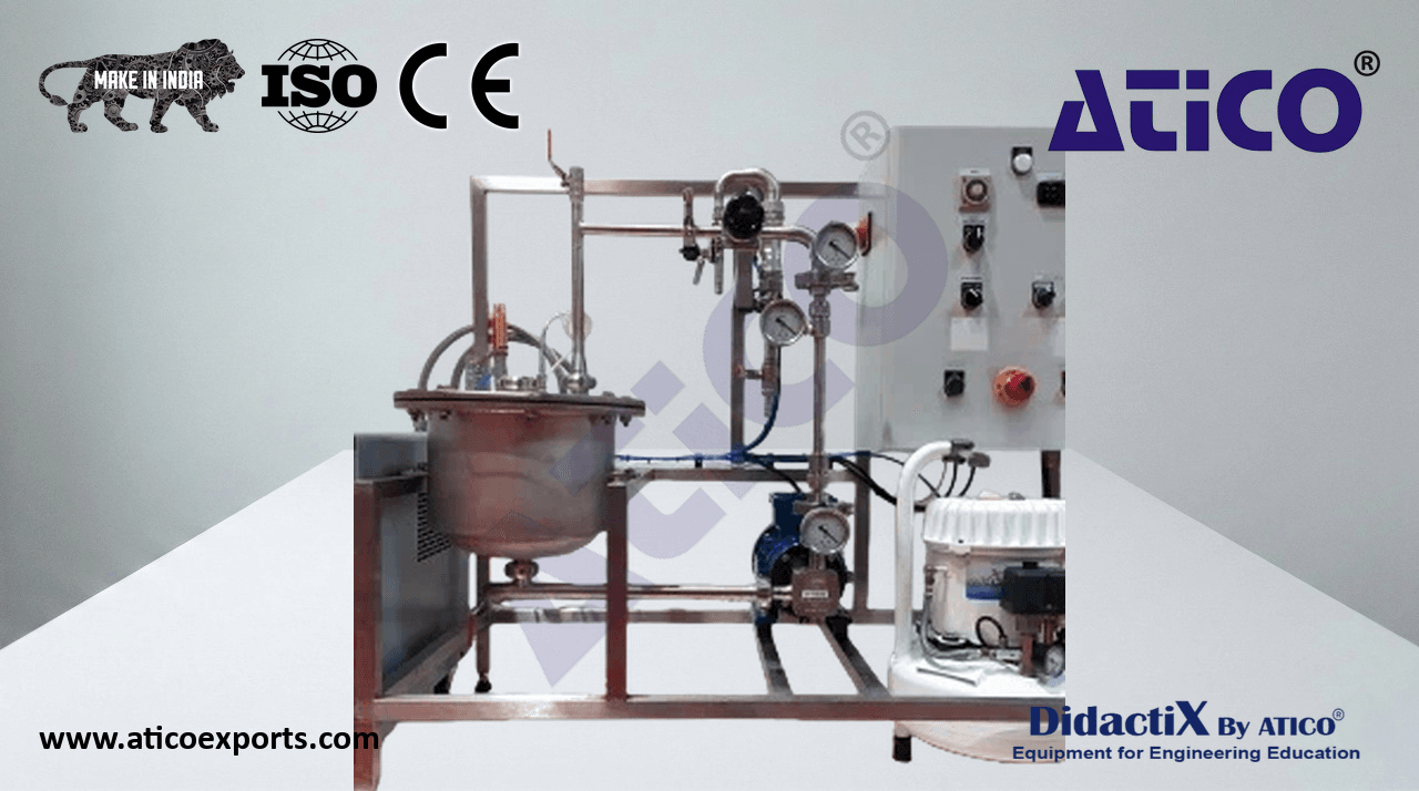
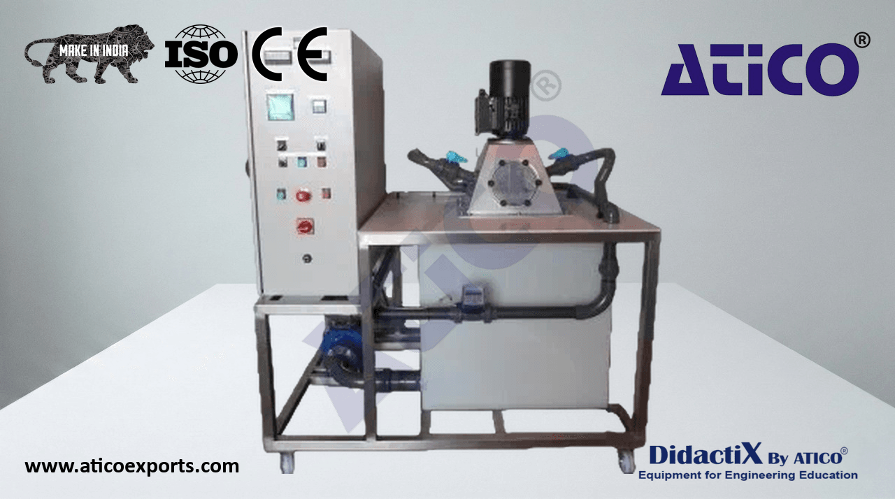
This educational micro hydroelectric power plant produces electrical energy from a Turgo-type turbine simulating a cascade of approximately 20 metres via a penstock. The operative section mounted on a stainless steel frame with castors comprises: approximately 300-litre thermoplastic tank with drain; stainless steel Turgo wheel with 22 nylon-6 blades and two interchangeable-nozzle injectors; 3 kW centrifugal pump (max.
One approximately 300-litre thermoplastic tank with drain valve.
One turbine fitted with a stainless steel Turgo wheel with 22 nylon-6 blades and two interchangeable-nozzle injectors.
One centrifugal pump, 3 kW power, max. flow rate approximately 60 m³/h.
One set of high-pressure PVC pipework to simulate the penstock.
One manual valve on the injector pipe.
One openable inspection window for turbine observation during operation and nozzle replacement.
The turbine drives an asynchronous generator of maximum 1.1 kW.
One paddle flow meter.
One needle pressure gauge (range: 0–2.5 bar).
One IP66 electrical cabinet comprising: generator speed display; potentiometer and frequency variable speed drive for pump speed adjustment; power analyser displaying voltage, power, cos φ, with three current transformers; start/stop button; emergency stop button; one user outlet.
Direct coupling: the generator is coupled to the distribution network when driven beyond its synchronisation speed, injecting energy into the network.
One capacitor bank for cos φ correction.