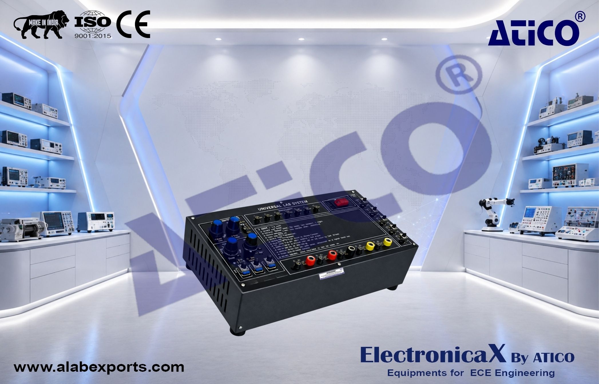
DC Power Supplies Module :
- Fixed Output: +5V/0.5A, -5V/0.5A, +12V/0.5A, -12V/0.5A
- Variable Output: +0V ~ +25V/0.5A, -0V ~ -25V/0.5A
AC Power Supplies Module :
Function Generator & Clock Generator Modules :
- Sine, Triangle and Square waveform output
- Frequency range: 1Hz to 1MHz in 6 decades
- With fine adjust, amplitude and DC offset control
- Clock output 1Hz to 1MHz in 6 decades
Six frequency ranges :
- 1Hz to 10Hz
- 10Hz to 100Hz
- 100Hz to 1KHz
- 1KHz to 10KHz
- 10KHz to 100KHz
- 100KHz to 100KHz
- Sine wave output: 0 to 12V peak to peak variable
- Triangle wave output: 0 to 8V peak to peak variable
- Square wave output: 0 to 22V peak to peak variable
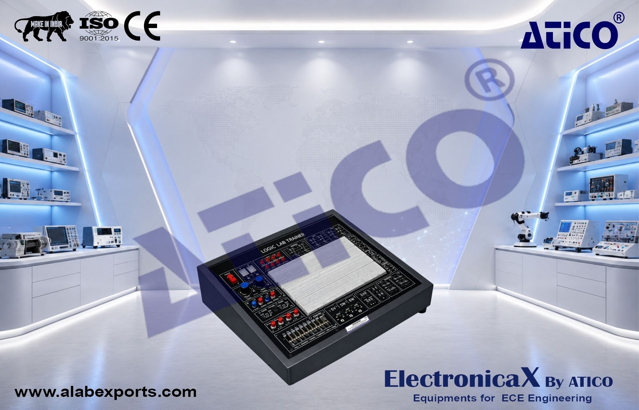
Solderless Breadboard Module :
- 1860 interconnected tie points
Pulse Switches Module :
- 80°s single shot pulse (positive & negative)
- Push button switches with debouncer
LED Indicators Module :
Data Output Switches Module :
TTL/CMOS Selection Switch :
Logic Probe Module :
- HI, LO, Float logic level testing
- CMOS / TTL level selection
Speaker Module :
Digital DC Voltmeter Module :
- 4 digits LED display
- Voltage ranges:
- 0V to 199.9VDC
- 0V to 19.99VDC
- 0V to 1.999VDC
- 0V to 199.9mVDC
- Input impedance: 10Mohm
Adaptors Module :
- 5 channels banana to 2mm adaptor interface socket
Experiments :
Analog Electronics Experiments :
The Superposition Theorem
- Capacitors in Voltage - Divider Networks
- Operational Amplifier - The Inverting Amplifier
- Operational Amplifier - The Non inverting Amplifier
- Operational Amplifier - The Comparator
- Operational Amplifier - The Summing Amplifier
- The Common - Base Amplifier Structure
- The Common - Emitter Amplifier Structure
- The Common - Collector Amplifier Structure
- The Op Amp Differentiator
- The Op Amp Integrator
- The RC Phase Shift Oscillator
- The As table Multivibrator
- The Schmitt Trigger
- The As table Multivibrator
- The D/A Converter
- The A/D Converter
Digital Electronics Experiments :
- Fundamental Logic Gate - AND, OR, NOR, XOR
- Fundamental Logic Gate - NAND, NOR, XOR
- Applications of Boolean Algebra
- De Morgan–s Law (I)
- De Morgan–s Law (II)
- Diode Resistor Logic - AND
- Exclusive OR
- Exclusive NOR
- Demultiplexer
- Synchronous Up - Counter
- Synchronous Down - Counter
- The Schmitt Trigger
- Oscillator – Counter
Accessories :
- Experiments manual, instruction manual with circuit diagram and power cord
Additional Details :
- Power Supply: 240VAC, 50Hz (Fused Protected)
- Dimensions: 310 x 260 x 90mm
- Weight: 3.5 kgs