ATENG 12656 — Applications for Process Control
FLOW
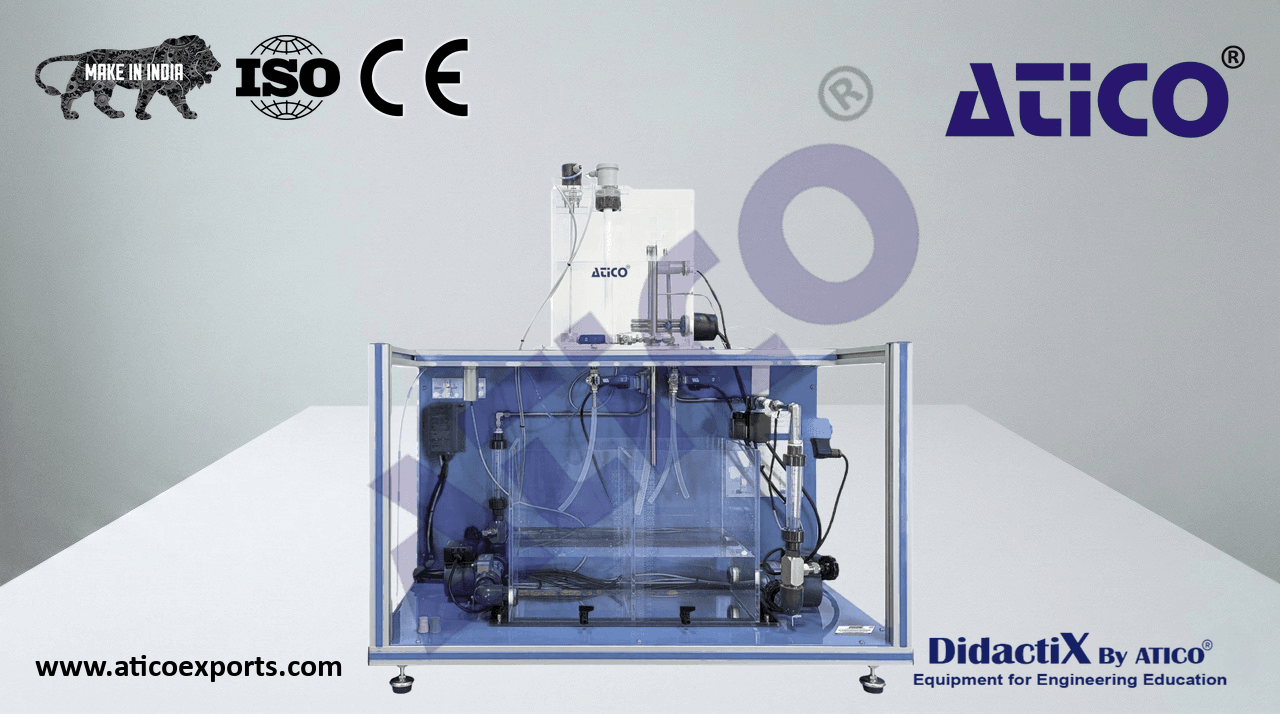
APC-FC. Computer Controlled Flow Regulation Application.
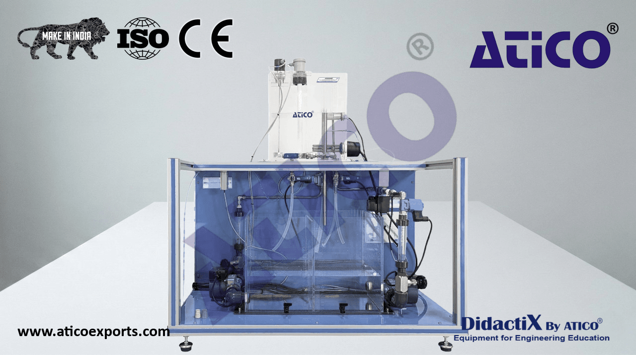
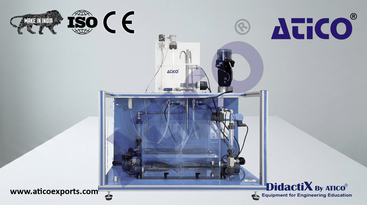
In the “APC-FC” application, a variable speed pump impels the water flow from a supply tank to a proportional valve and two flow sensors.
The control of the system is done through the “APC-FC-KAC” software.
- The elements included in the “APC-FC” application are:
- SU-H/S. Small Size Hydraulic Supply Unit.
Module designed to pump water to the other devices of the application. The variable speed pump included can be used as actuator
of the system.
- The elements included in the “SU-H/S” module are:
- Variable speed pump: 8 l/min approx.
- Plastic tank: 4 l approx.
Manual valve.
- N-ALI20. Power Supply Module for Control Circuits Module.
- Supply voltage (single-phase): 230 VAC, L+N+G.
Removable ON/OFF key switch.
- N-M-F-T/S. Turbine Type Sensor for Low Flow Rates.
- Maximum flow rate: 3 l/min approx.
- N-P-F-WR/S. Rotameter for Low Flow Hydraulic Circuit.
- Maximum flow rate: 4 l/min approx.
- APC-FC-KAC. Acquisition Kit and Control Software for APC-FC.
- The elements included in the “APC-FC-KAC” kit are:
USB Acquisition Card.
Data Acquisition and Control Software.
- The main functions of this software, based on LabVIEW, are:
Process signal visualization.
Data management and data storage.
ON/OFF and PID controls via software.
Tuning of the controller parameters.
- N-V-PR-W/S. Electromagnetic Proportional Valve for Low Flow Hydraulic Circuits.
Proportional valve that can be used to introduce disturbances in the system or as control device.
For the “APC-FC” application, there is available the optional “APC-FC-SIM”, Simulation Software for “APC-FC”. The “APC-FC-SIM”
- software is design to simulate the complete process of the application: the plant, the sensor and the controller. In order to simulate the
complete close control loop to adjust the controller in the software to understand the real process of the unit.
- APC-FC-SIM. Simulation Software for APC-FC.
- The main functions of this software, based on LabVIEW, are:
Process simulation.
Open loop system simulation.
Close loop system simulation.
PID controller simulation.
PID controller tuning of the close loop system simulation.
The elements recommended to extend the functionality of the “APC-FC” application are indicated in the table of available modules found
at the end of the document. In addition to the modules related to the flow control, it is possible to add modules related to other variables
to obtain multivariable control systems.
- Some practical possibilities of the “APC-FC” application:
- Design and assembly of the control system:
- Familiarization with the main components of a control system: sensor, actuator and controller.
- Preparation of the piping and instrumentation diagram (P&ID) of a flow control system.
- Preparation of connection, circuits, wiring and terminals diagrams of a flow control system.
- Assembly of the hydraulic circuit of a flow control system.
- Wiring of the control and measurement signals and the power supply of a flow control system.
- Analysis of the system and design of control strategies:
- Response of a flow control system to a step input.
- Simulation of a flow control system in open and closed loop (with optional “APC-FC-SIM”, Simulation Software for APC-FC).
- Effect of the parameters of a PID controller.
- PID control of a flow control system with the variable speed pump.
- PID control of a flow control system with the proportional valve.
- Response of the controlled system to disturbances and changes of the reference signal.
- Disturbance compensation through feedforward control.
3
AVAILABLE APPLICATIONS
FLOW
APC-FIC. Flow Regulation Application with Industrial Controller.
In the “APC-FIC” application, a pump impels water through a hydraulic circuit consisting of a supply tank, a rotameter and a motorized
valve. The control of the system is done through an industrial controller. In addition, a ball valve with scale is included to introduce
disturbances.
- The elements included in the “APC-FIC” application are:
- SU-H. Hydraulic Supply Unit.
Module designed to pump water to the other devices of the application. It is recommended for simple control applications, with only
one variable.
- The elements included in the “SU-H” module are:
- Centrifugal pump: 80 l/min approx.
- Stainless steel tank: 15 l approx.
Manual valve.
- N-ALI20. Power Supply Module for Control Circuits Module.
- Supply voltage (single-phase): 230 VAC, L+N+G.
Removable ON/OFF key switch.
- N-M-F-P. Paddlewheel Flow Sensor.
- Maximum flow rate: 50 l/min approx.
- N-V-MO. Motorized Control Valve.
- N-P-F-WR. Hydraulic Circuit Rotameter.
- The elements included in the “N-P-F-WR” module are:
- Rotameter: 50 l/min.
Regulation valve.
- N-IC. Industrial Controller.
USB Communication.
- Display: full-color LCD 9 cm (3.5 inches) with built-in backlight.
Configurable sample rate chart (1 second to 5 minutes).
- Control parameters:
- Control type:
ON/OFF control.
P, PI, PID control.
P, PI, PID control with gain scheduling (up to 3 set of PID parameters).
Predictive control (dead-time compensation).
Adaptive control.
P, PI and PID control with feedforward.
Cascade control.
Cascade control with feedforward.
Ratio controller.
Ratio station.
- Control output type:
Analog output.
Time proportioning output.
ON/OFF output.
Motorized valve with feedback.
Motorized valve without feedback.
Split output with combinations of relay, digital output and current outputs.
- Autotune function:
- On - demand calculation of control settings.
- Set points:
Configurable through the front panel or the computer.
Up to four local set points, all selectable via digital inputs or front panel.
8 Blocks math functions.
8 Blocks of logic functions.
2 Blocks of totalizer functions.
8 Blocks process alarms.
- 4 Analog inputs with 125 ms of sample rate.
- 2 Analog outputs.
4 Relays.
6 Digital I/O.
4
AVAILABLE APPLICATIONS
FLOW
- IC-KSS-SOF. Acquisition, Control and Controllers Configuration Software.
- The main functions of this software, based on LabVIEW, are:
- The following process variables can be visualize and managed via software:
Set point (SP) of the first and second control loop, output process (O/P) of the first and second control loop, process
variable (PV) of the first and second control loop.
Data visualization, data management and data storage of all process variables involved in the control loops.
- The following process parameters can be adjustable via software:
ON/OFF controller parameters, PID controller parameters of the one control loop or two control loops, set point values,
bias and slope ratio and Feedforward gain.
Besides, if other applications with industrial controllers are connected, the “IC-KSS-SOF” software can supervise all applications
connected, forming a distributed control system.
- N-V-H-S. Ball Valve with Scale.
Metering ball valve.
Scale from 90º (closed) to 0º (open).
The elements recommended to extend the functionality of the “APC-FIC” application are indicated in the table of available modules found
at the end of the document. In addition to the modules related to the flow control, it is possible to add modules related to other variables
to obtain multivariable control systems.
- Some practical possibilities of the “APC-FIC” application:
- Design and assembly of the control system:
- Familiarization with the main components of a control system: sensor, actuator and controller.
- Preparation of the piping and instrumentation diagram (P&ID) of a flow control system.
- Preparation of circuits, wiring, terminals and connection diagrams of a flow control system.
- Assembly of the hydraulic circuit of a flow control system.
- Wiring of the control and measurement signals and the power supply of a flow control system.
- Configuration of the system devices:
- Configuration of an industrial controller.
- Analysis of the system and design of control strategies:
- Manual control of the system with an industrial controller (open loop).
- Effect of the parameters of a PID controller.
- Obtaining the PID parameters automatically by auto-tuning.
- Adjustment and optimization of a PID controller.
- Response of the controlled system to disturbances and changes of the reference signal.
5
AVAILABLE APPLICATIONS
LEVEL
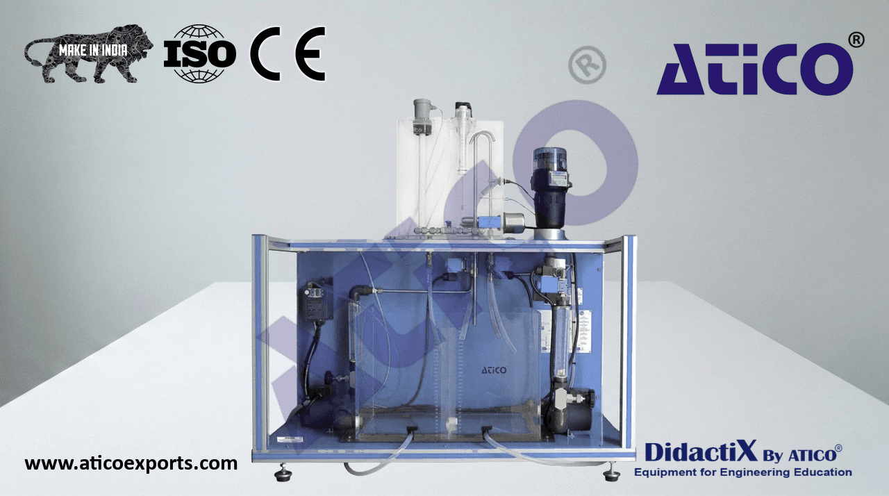
APC-LC. Computer Controlled Level Regulation Application.
In the “APC-LC” application, a variable speed pump impels water from a supply tank to an upper tank (process tank) where the level is
measured. The application includes a control valve, which can be configured in different points of the hydraulic circuit to regulate the
system or introduce disturbance. The control of the system is done through the “APC-LC-KAC” software.
- The elements included in the “APC-LC” application are:
- SU-H/S. Small Size Hydraulic Supply Unit.
Module designed to pump water to the other devices of the application. The variable speed pump included can be used as actuator
of the system.
- The elements included in the “SU-H/S” module are:
- Variable speed pump: 8 l/min approx.
- Plastic tank: 4 l approx.
Manual valve.
- N-ALI20. Power Supply Module for Control Circuits Module.
- Supply voltage (single-phase): 230 VAC, L+N+G.
Removable ON/OFF key switch.
- N-M-P-W/S. Pressure Sensor for Low Water Levels.
- Maximum pressure: 30 mbar approx.
- N-P-L-TT/S. Small Size Transparent Tank.
Transparent tank with graduated scale.
- Maximum level: 250 mm approx.
- APC-LC-KAC. Acquisition Kit and Control Software for APC-LC.
- The elements included in the “APC-LC-KAC” kit are:
USB Acquisition Card.
Data Acquisition and Control Software.
- The main functions of this software, based on LabVIEW, are:
Process signal visualization.
Data management and data storage.
ON/OFF and PID controls via software.
Tuning of the controller parameters.
- N-V-PR-W/S. Electromagnetic Proportional Valve for Low Flow Hydraulic Circuits.
Proportional valve that can be used to introduce disturbances in the system or as control device.
For the “APC-LC” application, there is available the optional “APC-LC-SIM”, Simulation Software for “APC-LC”. The “APC-LC-SIM”
- software is design to simulate the complete process of the application: the plant, the sensor and the controller. In order to simulate the
complete close control loop to adjust the controller in the software to understand the real process of the unit.
- APC-LC-SIM. Simulation Software for APC-LC.
- The main functions of this software, based on LabVIEW, are:
Process simulation.
Open loop system simulation.
Close loop system simulation.
PID controller simulation.
PID controller tuning of the close loop system simulation.
The elements recommended to extend the functionality of the “APC-LC” application are indicated in the table of available modules found
at the end of the document. In addition to the modules related to the level control, it is possible to add modules related to other variables
to obtain multivariable control systems.
- Some practical possibilities of the “APC-LC” application:
- Design and assembly of the control system:
- Familiarization with the main components of a control system: sensor, actuator and controller.
- Preparation of the piping and instrumentation diagram (P&ID) of a level control system.
- Preparation of circuits, wiring, terminals and connection diagrams of a level control system.
- Assembly of the hydraulic circuit of a level control system.
- Wiring of the control and measurement signals and the power supply of a level control system.
- Analysis of the system and design of control strategies:
- Response of a level control system to a step input.
- Simulation of a level control system in open and closed loop (with optional “APC-LC-SIM”, Simulation Software for APC-LC).
- Effect of the parameters of a PID controller.
- PID control of a level control system with the variable speed pump.
- PID control of a level control system with the proportional valve.
- Response of the controlled system to disturbances and changes of the reference signal.
- Disturbance compensation through feedforward control.
6
AVAILABLE APPLICATIONS
LEVEL
APC-LPRIC. Level Regulation Application with Industrial Controller and Proportional Valve.
In the “APC-LPRIC” application, a pump impels water through a hydraulic circuit consisting of a supply tank, a transparent tank with scale
and a proportional valve. The control of the system is done through an industrial controller. In addition, a ball valve with scale is included
to introduce disturbances.
- The elements included in the “APC-LPRIC” application are:
- SU-H. Hydraulic Supply Unit.
Module designed to pump water to the other devices of the application. It is recommended for simple control applications, with only
one variable.
- The elements included in the “SU-H” module are:
- Centrifugal pump: 80 l/min approx.
- Stainless steel tank: 15 l approx.
Manual valve.
- N-ALI20. Power Supply Module for Control Circuits Module.
- Supply voltage (single-phase): 230 VAC, L+N+G.
Removable ON/OFF key switch.
- N-M-P-W. Level Measurement Pressure Sensor.
- Maximum pressure: 100 mbar approx.
- N-V-PR-W. Electromagnetic Proportional Valve for Hydraulic Circuits.
- N-P-L-TT. Transparent Tank.
Transparent tank with graduated scale.
- Maximum level: 600 mm approx.
- N-IC. Industrial Controller.
USB Communication.
- Display: full-color LCD 9 cm (3.5 inches) with built-in backlight.
Configurable sample rate chart (1 second to 5 minutes).
- Control parameters:
- Control type:
ON/OFF control.
P, PI, PID control.
P, PI, PID control with gain scheduling (up to 3 set of PID parameters).
Predictive control (dead-time compensation).
Adaptive control.
P, PI and PID with feedforward.
Cascade control.
Cascade control with feedforward.
Ratio controller.
Ratio station.
- Control output type:
Analog output.
Time proportioning output.
ON/OFF output.
Motorized valve with feedback.
Motorized valve without feedback.
Split output with combinations of relay, digital output and current outputs.
- Autotune function:
- On - demand calculation of control settings.
- Set points:
Configurable through the front panel or the computer.
Up to four local set points, all selectable via digital inputs or front panel.
8 Blocks math functions.
8 Blocks of logic functions.
2 Blocks of totalizer functions.
8 Blocks process alarms.
- 4 Analog inputs with 125 ms of sample rate.
- 2 Analog outputs.
4 Relays.
6 Digital I/O.
7
AVAILABLE APPLICATIONS
LEVEL
- IC-KSS-SOF. Acquisition, Control and Controllers Configuration Software.
- The main functions of this software, based on LabVIEW, are:
- The following process variables can be visualize and managed via software:
Set point (SP) of the first and second control loop, output process (O/P) of the first and second control loop, process
variable (PV) of the first and second control loop.
Data visualization, data management and data storage of all process variables involved in the control loops.
- The following process parameters can be adjustable via software:
ON/OFF controller parameters, PID controller parameters of the one control loop or two control loops, set point values,
bias and slope ratio and Feedforward gain.
Besides, if other applications with industrial controllers are connected, the “IC-KSS-SOF” software can supervise all applications
connected, forming a distributed control system.
- N-V-H-S. Ball valve with Scale.
Metering ball valve.
Scale from 90º (closed) to 0º (open).
The elements recommended to extend the functionality of the “APC-LPRIC” application are indicated in the table of available modules
found at the end of the document. In addition to the modules related to the level control, it is possible to add modules related to other
variables to obtain multivariable control systems.
- Some practical possibilities of the “APC-LPRIC” application:
- Design and assembly of the control system:
- Familiarization with the main components of a control system: sensor, actuator and controller.
- Preparation of the piping and instrumentation diagram (P&ID) of a level control system.
- Preparation of circuits, wiring, terminals and connection diagrams of a level control system.
- Assembly of the hydraulic circuit of a level control system.
- Wiring of the control and measurement signals and the power supply of a level control system.
- Configuration of the system devices:
- Configuration of an industrial controller.
- Analysis of the system and design of control strategies:
- Manual control of the system with an industrial controller (open loop).
- Effect of the parameters of a PID controller.
- Obtaining the PID parameters automatically by auto-tuning.
- Adjustment and optimization of a PID controller.
- Response of the controlled system to disturbances and changes of the reference signal.
8
AVAILABLE APPLICATIONS
LEVEL
APC-LPNIC. Level Regulation Application with Industrial Controller and Pneumatic Valve.
In the “APC-LPNIC” application, a pump impels water through a hydraulic circuit consisting of a supply tank, a transparent tank with scale
and a pneumatic valve. The control of the system is done through an industrial controller. In addition, a ball valve with scale is included to
introduce disturbances and a signal recorder.
- The elements included in the “APC-LPNIC” application are:
- SU-H. Hydraulic Supply Unit.
Module designed to pump water to the other devices of the application. It is recommended for simple control applications, with only
one variable.
- The elements included in the “SU-H” module are:
- Centrifugal pump: 80 l/min approx.
- Stainless steel tank: 15 l approx.
Manual valve.
- N-ALI20. Power Supply Module for Control Circuits Module.
- Supply voltage (single-phase): 230 VAC, L+N+G.
Removable ON/OFF key switch.
- N-M-P-W. Level Measurement Pressure Sensor.
- Maximum pressure: 100 mbar approx.
- N-V-PN-W. Pneumatic Control Valve for Hydraulic Circuits.
- Pneumatic control valve:
Normally closed valve.
Linear plug.
Electro-pneumatic linear positioner.
- Control signals: 3 - 15 psi.
- Actuator: diaphragm type.
DN 20.
- Flow:
- Cv: 6.6 (referenced to USGPM and psi units).
- Kv: 5.7 (referenced to m3/h and bar units).
- Pressurized air inlet required: 2.5 bar.
- 2 Manometers:
- Pressure range: 0 - 10 bar.
Manual ball valve.
- N-ATC01: Air Filter and Pressure Regulator with Manometer Module.
- Air pressure inlet admitted range: 0 - 12 bar.
- Output pressure: 2.5 bar.
- Drain capacity: 12 cm3.
- N-P-L-TT. Transparent Tank.
Transparent tank with graduated scale.
- Maximum level: 600 mm approx.
- N-IC. Industrial Controller.
USB Communication.
- Display: full-color LCD 9 cm (3.5 inches) with built-in backlight.
Configurable sample rate chart (1 second to 5 minutes).
- Control parameters:
- Control type:
ON/OFF control.
P, PI, PID control.
P, PI, PID control with gain scheduling (up to 3 set of PID parameters).
Predictive control (dead-time compensation).
Adaptive control.
P, PI and PID control with feedforward.
Cascade control.
Cascade control with feedforward.
Ratio controller.
Ratio station.
9
AVAILABLE APPLICATIONS
LEVEL
- Control output type:
Analog output.
Time proportioning output.
ON/OFF output.
Motorized valve with feedback.
Motorized valve without feedback.
Split output with combinations of relay, digital output and current outputs.
- Autotune function:
- On - demand calculation of control settings.
- Set points:
Configurable through the front panel or the computer.
Up to four local set points, all selectable via digital inputs or front panel.
8 Blocks math functions.
8 Blocks of logic functions.
2 Blocks of totalizer functions.
8 Blocks process alarms.
- 4 Analog inputs with 125 ms of sample rate.
- 2 Analog outputs.
4 Relays.
6 Digital I/O.
- IC-KSS-SOF. Acquisition, Control and Controllers Configuration Software.
- The main functions of this software, based on LabVIEW, are:
- The following process variables can be visualize and managed via software:
Set point (SP) of the first and second control loop, output process (O/P) of the first and second control loop, process
variable (PV) of the first and second control loop.
Data visualization, data management and data storage of all process variables involved in the control loops.
- The following process parameters can be adjustable via software:
ON/OFF controller parameters, PID controller parameters of the one control loop or two control loops, set point values,
bias and slope ratio and Feedforward gain.
Besides, if other applications with industrial controllers are connected, the “IC-KSS-SOF” software can supervise all applications
connected, forming a distributed control system.
- N-V-H-S. Ball Valve with Scale.
Metering ball valve.
Scale from 90º (closed) to 0º (open).
- This application needs compressed air. The following accessory is recommended:
- SU-P. Large Pneumatic Supply Unit.
Module designed to supply compressed air to the rest of devices of the application.
- The elements included in the “SU-P” module are:
- Air compressor: 8 bar approx.
The elements recommended to extend the functionality of the “APC-LPNIC” application are indicated in the table of available modules
found at the end of the document. In addition to the modules related to the level control, it is possible to add modules related to other
variables to obtain multivariable control systems.
- Some practical possibilities of the “APC-LPNIC” application:
- Design and assembly of the control system:
- Familiarization with the main components of a control system: sensor, actuator and controller.
- Preparation of the piping and instrumentation diagram (P&ID) of a level control system.
- Preparation of circuits, wiring, terminals and connection diagrams of a level control system.
- Assembly of the hydraulic circuit of a level control system.
- Wiring of the control and measurement signals and the power supply of a level control system.
- Configuration of the system devices:
- Configuration of an industrial controller.
- Configuration of a signal recorder.
- Analysis of the system and design of control strategies:
- Manual control of the system with an industrial controller (open loop).
- Effect of the parameters of a PID controller.
- Obtaining the PID parameters automatically by auto-tuning.
- Adjustment and optimization of a PID controller.
- Response of the controlled system to disturbances and changes of the reference signal.
10
AVAILABLE APPLICATIONS
PRESSURE
APC-PHYC. Computer Controlled Pressure Regulation Application in a Hydraulic Circuit.
In the “APC-PHYC” application, a variable speed pump impels water from a supply tank to a pressurized upper tank where the pressure is
measured. The outlet of the process tank has a solenoid valve to regulate the system or introduce disturbances. The control of the system
is done through the “APC-PHYC-KAC” software.
- The elements included in the “APC-PHYC” application are:
- SU-H/S. Small Size Hydraulic Supply Unit.
Module designed to pump water to the other devices of the application. The variable speed pump included can be used as actuator
of the system.
- The elements included in the “SU-H/S” module are:
- Variable speed pump: 8 l/min approx.
- Plastic tank: 4 l approx.
Manual valve.
- N-ALI20. Power Supply Module for Control Circuits Module.
- Supply voltage (single-phase): 230 VAC, L+N+G.
Removable ON/OFF key switch.
- N-M-P-A/S. Compressed Air Low Pressure Sensor.
- Maximum pressure: 1 bar approx.
- N-P-L-PT/S. Small Size Pressurized Transparent Tank.
Pressurized transparent tank with graduated scale for level and pressure applications.
- Maximum level: 250 mm approx.
- APC-PHYC-KAC. Acquisition Kit and Control Software for APC-PHYC.
- The elements included in the “APC-PHYC-KAC” kit are:
USB Acquisition Card.
Data Acquisition and Control Software.
- The main functions of this software, based on LabVIEW, are:
Process signal visualization.
Data management and data storage.
ON/OFF and PID controls via software.
Tuning of the controller parameters.
- N-V-SO/S. Solenoid Valve for Low Flow Rates.
Solenoid valve that can be used to introduce disturbances in the system or as control device.
For the “APC-PHYC” application, there is available the optional “APC-PHYC-SIM”, Simulation Software for APC-PHYC. The “APC-PHYC-
- SIM” software is design to simulate the complete process of the application: the plant, the sensor and the controller. In order to simulate
the complete close control loop to adjust the controller in the software to understand the real process of the unit.
- APC-PHYC-SIM. Simulation Software for APC-PHYC.
- The main functions of this software, based on LabVIEW, are:
Process simulation.
Open loop system simulation.
Close loop system simulation.
PID controller simulation.
PID controller tuning of the close loop system simulation.
The elements recommended to extend the functionality of the “APC-PHYC” application are indicated in the table of available modules
found at the end of the document. In addition to the modules related to the pressure control, it is possible to add modules related to other
variables to obtain multivariable control systems.
- Some practical possibilities of the “APC-PHYC” application:
- Design and assembly of the control system:
- Familiarization with the main components of a control system: sensor, actuator and controller.
- Preparation of the piping and instrumentation diagram (P&ID) of a pressure control system.
- Preparation of circuits, wiring, terminals and connection diagrams of a pressure control system.
- Assembly of the hydraulic circuit of a pressure control system.
- Wiring of the control and measurement signals and the power supply of a pressure control system.
- Analysis of the system and design of control strategies:
- Response of a pressure control system to a step input.
- Simulation of a flow control system in open and closed loop (with optional “APC-PHYC-SIM”, Simulation Software for APC-PHYC).
- Effect of the parameters of a PID controller.
- ON/OFF control of a pressure control system with the solenoid valve.
- PID control of a pressure control system with the variable speed pump.
- Response of the controlled system to disturbances and changes of the reference signal.
11
AVAILABLE APPLICATIONS
PRESSURE
APC-PPNC. Computer Controlled Pressure Regulation Application in a Pneumatic Circuit.
In the “APC-PPNC” application, a variable speed gas pump fills a tank with compressed air. The outlet of the tank has a valve to introduce
disturbances. The control of the system is done through the “APC-PPNC-KAC” software.
- The elements included in the “APC-PPNC” application are:
- N-ALI20. Power Supply Module for Control Circuits Module.
- Supply voltage (single-phase): 230 VAC, L+N+G.
Removable ON/OFF key switch.
- N-SU-P/S. Small Size Pneumatic Supply Unit.
Module designed to pump air to the other devices of the application. The variable speed pump included can be used as actuator of
the system.
- The elements included in the “N-SU-P/S” module are:
Variable speed gas pump.
- Maximum flow: 3 l/min approx.
Manual valve.
- N-M-P-A/S. Compressed Air Low Pressure Sensor.
- Maximum pressure: 1 bar approx.
- N-P-P/S. Small Size Air Tank.
- The elements included in the “N-P-P/S” module are:
- Air tank: 400 ml approx.
- Manometer: 1 bar approx.
2 x relief valve.
- APC-PPNC-KAC. Acquisition Kit and Control Software for APC-PPNC.
- The elements included in the “APC-PPNC-KAC” kit are:
USB Acquisition Card.
Data Acquisition and Control Software.
- The main functions of this software, based on LabVIEW, are:
Process signal visualization.
Data management and data storage.
ON/OFF and PID controls via software.
Tuning of the controller parameters.
- N-V-SO/S. Solenoid Valve for Low Flow Rates.
Solenoid valve that can be used to introduce disturbances in the system or as control device.
For the “APC-PPNC” application, there is available the optional “APC-PPNC-SIM”, Simulation Software for APC-PPNC. The “APC-PPNC-SIM”
- software is design to simulate the complete process of the application: the plant, the sensor and the controller. In order to simulate the
complete close control loop to adjust the controller in the software to understand the real process of the unit.
- APC-PPNC-SIM. Simulation Software for APC-PPNC.
- The main functions of this software, based on LabVIEW, are:
Process simulation.
Open loop system simulation.
Close loop system simulation.
PID controller simulation.
PID controller tuning of the close loop system simulation.
The elements recommended to extend the functionality of the “APC-PPNC” application are indicated in the table of available modules
found at the end of the document. In addition to the modules related to the pressure control, it is possible to add modules related to other
variables to obtain multivariable control systems.
- Some practical possibilities of the “APC-PPNC” application:
- Design and assembly of the control system:
- Familiarization with the main components of a control system: sensor, actuator and controller.
- Preparation of the piping and instrumentation diagram (P&ID) of a pressure control system.
- Preparation of circuits, wiring, terminals and connection diagrams of a pressure control system.
- Assembly of the pneumatic circuit of a pressure control system.
- Wiring of the control and measurement signals and the power supply of a pressure control system.
- Analysis of the system and design of control strategies:
- Response of a pressure control system to a step input.
- Simulation of a pressure control system in open and closed loop (with optional “APC-PPNC-SIM”, Simulation Software for APC-
PPNC).
- Effect of the parameters of a PID controller.
- PID control of a pressure control system.
- Response of the controlled system to disturbances and changes of the reference signal.
12
AVAILABLE APPLICATIONS
PRESSURE
APC-PIC. Pressure Regulation Application with Industrial Controller.
In the “APC-PIC” application, the main compressed air circuit consists of a pneumatic valve and two tanks. The control of the system is
done through an industrial controller. In addition, a valve is included to introduce disturbances.
- The elements included in the “APC-PIC” application are:
- N-ALI20. Power Supply Module for Control Circuits Module.
- Supply voltage (single-phase): 230 VAC, L+N+G.
Removable ON/OFF key switch.
- N-M-P-A/L. Compressed Air Pressure Sensor for High Levels.
- Supply voltage: 24 VDC.
- Pressure range: 0 - 6 bar.
- Output voltage: 0 - 10 V.
- N-V-PN-A. Pneumatic Valve for Pneumatic Circuits.
Pneumatic regulation valve.
- 2 x N-ATC01: Air Filter and Pressure Regulator with Manometer Module.
- Air pressure inlet admitted range: 0 - 12 bar.
- Output pressure: 2.5 bar.
- Drain capacity: 12 cm3.
- 2 x N-P-P/L. Large Air Tank.
- The elements included in the “N-P-P/L” module are:
- Compressed air tank: 10 l approx.
- Manometer: 12 bar approx.
Needle valve.
- N-IC. Industrial Controller.
USB Communication.
- Display: full-color LCD 9 cm (3.5 inches) with built-in backlight.
Configurable sample rate chart (1 second to 5 minutes).
- Control parameters:
- Control type:
ON/OFF control.
P, PI, PID control.
P, PI, PID control with gain scheduling (up to 3 set of PID parameters).
Predictive control (dead-time compensation).
Adaptive control.
P, PI and PID control with feedforward.
Cascade control.
Cascade control with feedforward.
Ratio controller.
Ratio station.
- Control output type:
Analog output.
Time proportioning output.
ON/OFF output.
Motorized valve with feedback.
Motorized valve without feedback.
Split output with combinations of relay, digital output and current outputs.
- Autotune function:
- On - demand calculation of control settings.
- Set points:
Configurable through the front panel or the computer.
Up to four local set points, all selectable via digital inputs or front panel.
13
AVAILABLE APPLICATIONS
PRESSURE
8 Blocks math functions.
8 Blocks of logic functions.
2 Blocks of totalizer functions.
8 Blocks process alarms.
- 4 Analog inputs with 125 ms of sample rate.
- 2 Analog outputs.
4 Relays.
6 Digital I/O.
- IC-KSS-SOF. Acquisition, Control and Controllers Configuration Software.
- The main functions of this software, based on LabVIEW, are:
- The following process variables can be visualize and managed via software:
Set point (SP) of the first and second control loop, output process (O/P) of the first and second control loop, process
variable (PV) of the first and second control loop.
Data visualization, data management and data storage of all process variables involved in the control loops.
- The following process parameters can be adjustable via software:
ON/OFF controller parameters, PID controller parameters of the one control loop or two control loops, set point values,
bias and slope ratio and Feedforward gain.
Besides, if other applications with industrial controllers are connected, the “IC-KSS-SOF” software can supervise all applications
connected, forming a distributed control system.
- This application needs compressed air. The following accessory is recommended:
- SU-P. Large Pneumatic Supply Unit.
Module designed to supply compressed air to the rest of devices of the application.
- The elements included in the “SU-P” module are:
- Air compressor: 8 bar approx.
The elements recommended to extend the functionality of the “APC-PIC” application are indicated in the table of available modules found
at the end of the document. In addition to the modules related to the pressure control, it is possible to add modules related to other
variables to obtain multivariable control systems.
- Some practical possibilities of the “APC-PIC” application:
- Design and assembly of the control system:
- Familiarization with the main components of a control system: sensor, actuator and controller.
- Preparation of the piping and instrumentation diagram (P&ID) of a pressure control system.
- Preparation of circuits, wiring, terminals and connection diagrams of a pressure control system.
- Assembly of the pneumatic circuit of a pressure control system.
- Wiring of the control and measurement signals and the power supply of a pressure control system.
- Configuration of the system devices:
- Configuration of an industrial controller.
- Analysis of the system and design of control strategies:
- Manual control of the system with an industrial controller (open loop).
- Effect of the parameters of a PID controller.
- Obtaining the PID parameters automatically by auto-tuning.
- Adjustment and optimization of a PID controller.
- Response of the controlled system to disturbances and changes of the reference signal.
14
AVAILABLE APPLICATIONS
TEMPERATURE
APC-TPRIC. Temperature Regulation Application with Industrial Controller and Proportional Valve.
The “APC-TPRIC” application consists of a hot water circuit, a cold water circuit and an exchanger that transfers the heat between both
circuits. In the hot water circuit, a pump impels the water from the supply tank to the exchanger, passing through a heating element and
a control valve. From the exchanger, the water returns to the supply tank, closing the circuit. Tap water is used as cold water source. Both
circuits include rotameters and valves to adjust the flow rate.
The modular design of the “APC-TPRIC” application makes it possible to measure and control the temperature in different points of the
system. Besides, a valve with scale introduces disturbances.
- The elements included in the “APC-TPRIC” application are:
- SU-H. Hydraulic Supply Unit.
Module designed to pump water to the other devices of the application. It is recommended for simple control applications, with only
one variable.
- The elements included in the “SU-H” module are:
- Centrifugal pump: 80 l/min approx.
- Stainless steel tank: 15 l approx.
Manual valve.
- N-ALI20. Power Supply Module for Control Circuits Module.
- Supply voltage (single-phase): 230 VAC, L+N+G.
Removable ON/OFF key switch.
- N-M-T-PT100. Pt100 Temperature Sensor.
- Range: -50 - 400 °C.
- N-H-2K. 2 kW Heating Module.
- Heating resistance:
- Supply voltage (single-phase): 220 VAC.
- Maximum power: 2 kW.
Safety temperature switch.
- Safety temperature sensor:
- Transducer type: thermocouple type “J”.
- Temperature range: -100 - 900 ºC.
- Accuracy: ± 1 ºC.
Safety low level switch.
- Safety relief valve:
- Pressure setting: 3 bar.
Discharge line.
Additional manual opening system.
- Manometer:
- Pressure range: 0 - 4 bar.
Automatic air vent valve.
Control module box.
- 2 kW power control driver.
Based on Solid State Relay (SSR).
- 24 VDC Digital input.
- Safety temperature controller:
ON/OFF control.
- Set temperature: 65 ºC.
Safety stop input for low level switch.
- N-P-T-WW. Water-Water Heat Exchanger.
- The elements included in the “N-P-T-WW” module are:
Heat exchanger.
- Type: plate heat exchanger.
2 Manual ball valves.
- 2 Analog flow meter:
- Flow range: 0 - 2 l/min.
- 4 N-M-T-JT: “J Type” thermocouple.
- Transducer type: thermocouple type “J”.
- Temperature range: -100 - 900 ºC.
- Accuracy: ± 1 ºC.
- 4 Temperature analogs:
- Temperature range: 0 - 120 ºC.
- Accuracy: ± 1 ºC.
15
AVAILABLE APPLICATIONS
TEMPERATURE
- N-IC. Industrial Controller.
USB Communication.
- Display: full-color LCD 9 cm (3.5 inches) with built-in backlight.
Configurable sample rate chart (1 second to 5 minutes).
- Control parameters:
- Control type:
ON/OFF control.
P, PI, PID control.
P, PI, PID control with gain scheduling (up to 3 set of PID parameters).
Predictive control (dead-time compensation).
Adaptive control.
P, PI and PID control with feedforward.
Cascade control.
Cascade control with feedforward.
Ratio controller.
Ratio station.
- Control output type:
Analog output.
Time proportioning output.
ON/OFF output.
Motorized valve with feedback.
Motorized valve without feedback.
Split output with combinations of relay, digital output and current outputs.
- Autotune function:
- On - demand calculation of control settings.
- Set points:
Configurable through the front panel or the computer.
Up to four local set points, all selectable via digital inputs or front panel.
8 Blocks math functions.
8 Blocks of logic functions.
2 Blocks of totalizer functions.
8 Blocks process alarms.
- 4 Analog inputs with 125 ms of sample rate.
- 2 Analog outputs.
4 Relays.
6 Digital I/O.
- IC-KSS-SOF. Acquisition, Control and Controllers Configuration Software.
- The main functions of this software, based on LabVIEW, are:
- The following process variables can be visualize and managed via software:
Set point (SP) of the first and second control loop, output process (O/P) of the first and second control loop, process
variable (PV) of the first and second control loop.
Data visualization, data management and data storage of all process variables involved in the control loops.
- The following process parameters can be adjustable via software:
ON/OFF controller parameters, PID controller parameters of the one control loop or two control loops, set point values,
bias and slope ratio and Feedforward gain.
Besides, if other applications with industrial controllers are connected, the “IC-KSS-SOF” software can supervise all applications
connected, forming a distributed control system.
16
AVAILABLE APPLICATIONS
TEMPERATURE
- N-V-H-S. Ball Valve with Scale.
Metering ball valve.
Scale from 90º (closed) to 0º (open).
- N-V-PR-W. Electromagnetic Proportional Valve for Hydraulic Circuits.
The elements recommended to extend the functionality of the “APC-TPRIC” application are indicated in the table of available modules
found at the end of the document. In addition to the modules related to the temperature control, it is possible to add modules related to
other variables to obtain multivariable control systems.
- Some practical possibilities of the “APC-TPRIC” application:
- Design and assembly of the control system:
- Familiarization with the main components of a control system: sensor, actuator and controller.
- Preparation of the piping and instrumentation diagram (P&ID) of a temperature control system.
- Preparation of circuits, wiring, terminals and connection diagrams of a temperature control system.
- Assembly of the hydraulic circuit of a temperature control system.
- Wiring of the control and measurement signals and the power supply of a temperature control system.
- Configuration of the system devices:
- Configuration of an industrial controller.
- Analysis of the system and design of control strategies:
- Manual control of the system with an industrial controller (open loop).
- Effect of the parameters of a PID controller.
- Obtaining the PID parameters automatically by auto-tuning.
- Adjustment and optimization of a PID controller.
- Response of the controlled system to disturbances and changes of the reference signal.
17
AVAILABLE APPLICATIONS
TEMPERATURE
APC-TFAIC. Temperature Regulation Application with Industrial Controller and Fan.
In the “APC-TFAIC” application, a pump impels water through a hydraulic circuit consisting of a heating device, which heats water, and an
air-water exchanger, which cools the fluid down with a fan. Both the fan and the heating element can be used to control the temperature.
The application includes three thermocouples to measure the temperature in various points of the circuit and a system of tubes to study
delays. In addition, a valve with scale introduces disturbances.
- The elements included in the “APC-TFAIC” application are:
- N-SU-H-HW. Hot Water Pumping Unit.
Water pumping unit designed for temperature control applications.
- The elements included in the “N-SU-H-HW” module are:
- Circulation pump:
- Supply voltage: single-phase 230 VAC.
- Nominal power: 103 W.
- Nominal flow: 10 - 63.2 l/min.
- Maximum operating pressure: 10 bar.
N-V-H-S. Ball Valve with Scale.
Metering ball valve.
Scale from 90º (closed) to 0º (open).
- N-ALI20. Power Supply Module for Control Circuits Module.
- Supply voltage (single-phase): 230 VAC, L+N+G.
Removable ON/OFF key switch.
- N-M-T-JT. “J type” Thermocouple.
- Transducer type: thermocouple type “J”.
- Temperature range: -100 - 900 ºC.
- Accuracy: ± 1 ºC.
- N-H-2K. 2 kW Heating Module.
- Heating resistance:
- Supply voltage (single-phase): 220 VAC.
- Maximum power: 2 kW.
Safety temperature switch.
- Safety temperature sensor:
- Transducer type: thermocouple type “J”.
- Temperature range: -100 - 900 ºC.
- Accuracy: ± 1 ºC.
Safety low level switch.
- Safety relief valve:
- Pressure setting: 3 bar.
Discharge line.
Additional manual opening system
- Manometer:
- Pressure range: 0 - 4 bar.
Automatic air vent valve.
Control module box.
- 2 kW power control driver.
Based on Solid State Relay (SSR).
18
AVAILABLE APPLICATIONS
TEMPERATURE
- 24 VDC Digital input.
- Safety temperature controller:
ON/OFF control.
- Set temperature: 65 ºC.
Safety stop input for low level switch.
- N-P-T-AW. Air-Water Heat Exchanger.
The fan of the air-water exchanger included may be used as actuator of the system.
- The elements included in the “N-P-T-AW” module are:
Air-water heat exchanger with fan.
2 x needle thermometer of 80 °C approx.
- N-IC. Industrial Controller.
USB Communication.
- Display: full-color LCD 9 cm (3.5 inches) with built-in backlight.
Configurable sample rate chart (1 second to 5 minutes).
- Control parameters:
- Control type:
ON/OFF control.
P, PI, PID control.
P, PI, PID control with gain scheduling (up to 3 set of PID parameters).
Predictive control (dead-time compensation).
Adaptive control.
P, PI and PID control with feedforward.
Cascade control.
Cascade control with feedforward.
Ratio controller.
Ratio station.
- Control output type:
Analog output.
Time proportioning output.
ON/OFF output.
Motorized valve with feedback.
Motorized valve without feedback.
Split output with combinations of relay, digital output and current outputs.
- Autotune function:
- On - demand calculation of control settings.
- Set points:
Configurable through the front panel or the computer.
Up to four local set points, all selectable via digital inputs or front panel.
8 Blocks math functions.
8 Blocks of logic functions.
2 Blocks of totalizer functions.
8 Blocks process alarms.
- 4 Analog inputs with 125 ms of sample rate.
- 2 Analog outputs.
4 Relays.
6 Digital I/O.
19
AVAILABLE APPLICATIONS
TEMPERATURE
- IC-KSS-SOF. Acquisition, Control and Controllers Configuration Software.
- The main functions of this software, based on LabVIEW, are:
- The following process variables can be visualize and managed via software:
Set point (SP) of the first and second control loop, output process (O/P) of the first and second control loop, process
variable (PV) of the first and second control loop.
Data visualization, data management and data storage of all process variables involved in the control loops.
- The following process parameters can be adjustable via software:
ON/OFF controller parameters, PID controller parameters of the one control loop or two control loops, set point values,
bias and slope ratio and Feedforward gain.
Besides, if other applications with industrial controllers are connected, the “IC-KSS-SOF” software can supervise all applications
connected, forming a distributed control system.
- N-DELAY. Delay Time Module.
The elements recommended to extend the functionality of the “APC-TFAIC” application are indicated in the table of available modules
found at the end of the document. In addition to the modules related to the temperature control, it is possible to add modules related to
other variables to obtain multivariable control systems.
- Some practical possibilities of the “APC-TFAIC” application:
- Design and assembly of the control system:
- Familiarization with the main components of a control system: sensor, actuator and controller.
- Preparation of the piping and instrumentation diagram (P&ID) of a temperature control system.
- Preparation of circuits, wiring, terminals and connection diagrams of a temperature control system.
- Assembly of the hydraulic circuit of a temperature control system.
- Wiring of the control and measurement signals and the power supply of a temperature control system.
- Configuration of the system devices:
- Configuration of an industrial controller.
- Configuration of a signal recorder.
- Analysis of the system and design of control strategies:
- Manual control of the system with an industrial controller (open loop).
- Effect of the parameters of a PID controller.
- Obtaining the PID parameters automatically by auto-tuning.
- Adjustment and optimization of a PID controller.
- Effect of the delay time.
- Response of the controlled system to disturbances and changes of the reference signal.
20
AVAILABLE APPLICATIONS
pH
APC-PHIC. pH Regulation Application with Industrial Controller.
In the “APC-PHIC” application, an alkali is added to the tap water by a dosing pump and the pH is measured. Then, a second dosing
pump adds an acid to the solution.
The control of the system is done through an industrial controller that acts on one of the pumps. Disturbances can be introduced into the
system with the other pump or with a valve at the water inlet. In addition, a manual pH meter is included to remove the products and a
signal recorder.
- The elements included in the “APC-PHIC” application are:
- 2 x N-SU-C. Chemicals Supply Unit.
Module designed to pump reagents to the other devices of the application. The variable speed pump included can be used as actuator
of the system.
- The elements included in the “N-SU-C” module are:
- Dosing pump: 2 l/h approx.
- Plastic tank: 5 l approx.
Manual valve.
- N-ALI20. Power Supply Module for Control Circuits Module.
- Supply voltage (single-phase): 230 VAC, L+N+G.
Removable ON/OFF key switch.
- 2 x N-M-PH. pH Sensor.
- Range: 1 - 12.
- N-P-PH. Tanks for pH Measurement.
- The elements included in the “N-P-PH” module are:
2 x transparent tanks for pH measurement.
2 x mixing nozzles.
- Rotameter: 4 l/min.
Regulation valve.
Tank for chemical products.
- N-IC. Industrial Controller.
USB Communication.
- Display: full-color LCD 9 cm (3.5 inches) with built-in backlight.
Configurable sample rate chart (1 second to 5 minutes).
- Control parameters:
- Control type:
ON/OFF control.
P, PI, PID control.
P, PI, PID control with gain scheduling (up to 3 set of PID parameters).
Predictive control (dead-time compensation).
Adaptive control.
P, PI and PID control with feedforward.
Cascade control.
Cascade control with feedforward.
Ratio controller.
Ratio station.
- Control output type:
Analog output.
Time proportioning output.
ON/OFF output.
Motorized valve with feedback.
Motorized valve without feedback.
Split output with combinations of relay, digital output and current outputs.
- Autotune function:
- On - demand calculation of control settings.
- Set points:
Configurable through the front panel or the computer.
Up to four local set points, all selectable via digital inputs or front panel.
21
AVAILABLE APPLICATIONS
pH
8 Blocks math functions.
8 Blocks of logic functions.
2 Blocks of totalizer functions.
8 Blocks process alarms.
- 4 Analog inputs with 125 ms of sample rate.
- 2 Analog outputs.
4 Relays.
6 Digital I/O.
- IC-KSS-SOF. Acquisition, Control and Controllers Configuration Software.
- The main functions of this software, based on LabVIEW, are:
- The following process variables can be visualize and managed via software:
Set point (SP) of the first and second control loop, output process (O/P) of the first and second control loop, process
variable (PV) of the first and second control loop.
Data visualization, data management and data storage of all process variables involved in the control loops.
- The following process parameters can be adjustable via software:
ON/OFF controller parameters, PID controller parameters of the one control loop or two control loops, set point values,
bias and slope ratio and Feedforward gain.
Besides, if other applications with industrial controllers are connected, the “IC-KSS-SOF” software can supervise all applications
connected, forming a distributed control system.
- N-SR-2. Two-channel Signal Recorder Module.
- 2 x N-DD. Digital Display.
- N-M-PH-HH. Handheld pH Meter.
- Required consumables (not included):
- Caustic soda 45 % (NaOH).
- Hydrochloric acid 30 % (HCl).
The elements recommended to extend the functionality of the “APC-PHIC” application are indicated in the table of available modules found
at the end of the document. In addition to the modules related to the pH control, it is possible to add modules related to other variables
to obtain multivariable control systems.
- Some practical possibilities of the “APC-PHIC” application:
- Design and assembly of the control system:
- Familiarization with the main components of a control system: sensor, actuator and controller.
- Preparation of the piping and instrumentation diagram (P&ID) of a pH control system.
- Preparation of circuits, wiring, terminals and connection diagrams of a pH control system.
- Assembly of the hydraulic circuit of a pH control system.
- Wiring of the control and measurement signals and the power supply of a pH control system.
- Configuration of the system devices:
- Configuration of an industrial controller.
- Analysis of the system and design of control strategies:
- Manual control of the system with an industrial controller (open loop).
- Effect of the parameters of a PID controller.
- Obtaining the PID parameters automatically by auto-tuning.
- Adjustment and optimization of a PID controller.
- Response of the controlled system to disturbances and changes of the reference signal.
22
AVAILABLE APPLICATIONS
APC-FLIC. Flow and Level Regulation Application with Industrial Controller.
In the “APC-FLIC” application, a pump impels water through a hydraulic circuit consisting of a supply tank, a rotameter, a transparent tank
and a proportional valve. The unit includes two industrial controllers that can be configured to control two independent control loops or
as a cascade control system. Besides, two valves with scale introduce disturbances to the system.
- The elements included in the “APC-FLIC” application are:
- SU-H. Hydraulic Supply Unit.
Module designed to pump water to the other devices of the application. It is recommended for simple control applications, with only
one variable.
- The elements included in the “SU-H” module are:
- Centrifugal pump: 80 l/min approx.
- Stainless steel tank: 15 l approx.
Manual valve.
- N-ALI20. Power Supply Module for Control Circuits Module.
- Supply voltage (single-phase): 230 VAC, L+N+G.
Removable ON/OFF key switch.
- N-M-F-E. Electromagnetic Flow Sensor.
- Magnetic-inductive flow sensor:
- Supply voltage: 18 - 30 VDC.
- Flow range: 0 - 50 l/min.
- Accuracy: ± 0.8 % of the measured value + 0.5 l/min.
- Repeatability: ± 0.2 l/min.
- Response time: 0.15 s.
- N-M-P-W. Level Measurement Pressure Sensor.
- Maximum pressure: 100 mbar approx.
- N-V-PR-W. Electromagnetic Proportional Valve for Hydraulic Circuits.
- N-P-F-WR. Hydraulic Circuit Rotameter.
- The elements included in the “N-P-F-WR” module are:
- Rotameter: 50 l/min approx.
Regulation valve.
- N-P-L-TT. Transparent Tank.
Transparent tank with graduated scale.
- Maximum level: 600 mm approx.
- 2 x N-IC. Industrial Controller.
USB Communication.
- Display: full-color LCD 9 cm (3.5 inches) with built-in backlight.
Configurable sample rate chart (1 second to 5 minutes).
- Control parameters:
- Control type:
ON/OFF control.
P, PI, PID control.
P, PI, PID control with gain scheduling (up to 3 set of PID parameters).
Predictive control (dead-time compensation).
Adaptive control.
P, PI and PID control with feedforward.
Cascade control.
Cascade control with feedforward.
Ratio controller.
Ratio station.
- Control output type:
Analog output.
Time proportioning output.
ON/OFF output.
Motorized valve with feedback.
Motorized valve without feedback.
Split output with combinations of relay, digital output and current outputs.
- Autotune function:
- On - demand calculation of control settings.
- Set points:
Configurable through the front panel or the computer.
Up to four local set points, all selectable via digital inputs or front panel.
23
AVAILABLE APPLICATIONS
8 Blocks math functions.
8 Blocks of logic functions.
2 Blocks of totalizer functions.
8 Blocks process alarms.
- 4 Analog inputs with 125 ms of sample rate.
- 2 Analog outputs.
4 Relays.
6 Digital I/O.
- IC-KSS-SOF. Acquisition, Control and Controllers Configuration Software.
- The main functions of this software, based on LabVIEW, are:
- The following process variables can be visualize and managed via software:
Set point (SP) of the first and second control loop, output process (O/P) of the first and second control loop, process
variable (PV) of the first and second control loop.
Data visualization, data management and data storage of all process variables involved in the control loops.
- The following process parameters can be adjustable via software:
ON/OFF controller parameters, PID controller parameters of the one control loop or two control loops, set point values,
bias and slope ratio and Feedforward gain.
Besides, if other applications with industrial controllers are connected, the “IC-KSS-SOF” software can supervise all applications
connected, forming a distributed control system.
- 2 x N-V-H-S. Ball Valve with Scale.
Metering ball valve.
Scale from 90º (closed) to 0º (open).
The elements recommended to extend the functionality of the “APC-FLIC” application are indicated in the table of available modules found
at the end of the document. In addition to the modules related to the pH control, it is possible to add modules related to other variables
to obtain multivariable control systems.
- Some practical possibilities of the “APC-FLIC” application:
- Design and assembly of the control system:
- Familiarization with the main components of a control system: sensor, actuator and controller.
- Preparation of the piping and instrumentation diagram (P&ID) of a flow and level control system.
- Preparation of circuits, wiring, terminals and connection diagrams of a flow and level control system.
- Assembly of the hydraulic circuit of a flow and level control system.
- Wiring of the control and measurement signals and the power supply of a flow and level control system.
- Configuration of the system devices:
- Configuration of an industrial controller.
- Analysis of the system and design of control strategies:
- Manual control of the system with an industrial controller (open loop).
- Effect of the parameters of a PID controller.
- Obtaining the PID parameters automatically by auto-tuning.
- Adjustment and optimization of a PID controller to regulate flow.
- Adjustment and optimization of a PID controller to regulate a cascade flow and level system.
- Response of the controlled system to disturbances and changes of the reference signal.
24
AVAILABLE APPLICATIONS
APC-LPIC. Level and Pressure Regulation Application with Industrial Controller.
In the “APC-LPIC” application, a water jet pump generates vacuum in a pressurized tank, absorbing a mixture of water and air that,
due to the generated depression, allows the extraction of gases dissolved in the water. To achieve this goal, the pressure and level in the
pressurized tank must meet some specifications.
However, acting on any of these variables affects the control of the other.
With the Level and Pressure Regulation Application with Industrial Controller, “APC-LPIC”, the student will check in a real system the
interactions between different control loops and learn to uncouple them through multivariable control strategies.
- The elements included in the “APC-LPIC” application are:
- SU-H/L. Large Hydraulic Supply Unit.
Module designed to pump water to the other devices of the application. It is recommended for multivariable control applications.
- The elements included in the “SU-H/L” module are:
- Reservoir tank:
- Capacity: 100 l.
Safety low level switch.
Refrigeration circuit.
Temperature gauge.
- Centrifugal pump:
- Supply voltage: 230 VAC three-phase.
- Nominal power: 1.1 kW.
- Nominal flow: 100 l/min.
- SU-H-AP/L. Auxiliary High Flow Rate Centrifugal Pump.
Auxiliary pump designed for the study of the coupling of pumps in series and parallel or for complex control systems that require
different pumps. This module is recommended for working together with the “SU-H/L” water supply unit.
- Maximum flow: 90 l/min approx.
- N-ALI20. Power Supply Module for Control Circuits Module.
- Supply voltage (single-phase): 230 VAC, L+N+G.
Removable ON/OFF key switch.
- N-M-L-C. Capacitive Level Sensor.
- Maximum height: 480 mm approx.
- N-M-P-V. Vacuum Pressure Sensor.
- Range: -1 - 600 mbar approx.
- 2 x N-V-PN-W. Pneumatic Control Valve for Hydraulic Circuits.
- Pneumatic control valve:
Normally closed valve.
Linear plug.
Electro-pneumatic linear positioner.
- Control signals: 3 - 15 psi.
- Actuator: diaphragm type.
DN 20.
- Flow:
- Cv: 6.6 (referenced to USGPM and psi units)
- Kv: 5.7 (referenced to m3/h and bar units)
- Pressurized air inlet required: 2.5 bar.
- 2 Manometers:
- Pressure range: 0 - 10 bar.
Manual ball valve.
- N-ATC01: Air Filter and Pressure Regulator with Manometer Module.
- Air pressure inlet admitted range: 0 - 12 bar.
- Output pressure: 2.5 bar.
- Drain capacity: 12 cm3.
- N-P-F-WR. Hydraulic Circuit Rotameter.
- The elements included in the “N-P-F-WR” module are:
- Rotameter: 50 l/min.
Regulation valve.
25
AVAILABLE APPLICATIONS
- N-P-L-PT. Pressurized Transparent Tank.
Pressurized transparent tank with graduated scale for level and pressure applications.
- The elements included in the “N-P-L-PT” module are:
- Pressurized transparent tank: 500 mm approx.
- Manometer: 2.5 bar approx.
Safety valve.
- 2 x N-IC. Industrial Controller.
USB Communication.
- Display: full-color LCD 9 cm (3.5 inches) with built-in backlight.
Configurable sample rate chart (1 second to 5 minutes).
- Control parameters:
- Control type:
ON/OFF control.
P, PI, PID control.
P, PI, PID control with gain scheduling (up to 3 set of PID parameters).
Predictive control (dead-time compensation).
Adaptive control.
P, PI and PID control with feedforward.
Cascade control.
Cascade control with feedforward.
Ratio controller.
Ratio station.
- Control output type:
Analog output.
Time proportioning output.
ON/OFF output.
Motorized valve with feedback.
Motorized valve without feedback.
Split output with combinations of relay, digital output and current outputs.
- Autotune function:
- On - demand calculation of control settings.
- Set points:
Configurable through the front panel or the computer.
Up to four local set points, all selectable via digital inputs or front panel.
8 Blocks math functions.
8 Blocks of logic functions.
2 Blocks of totalizer functions.
8 Blocks process alarms.
- 4 Analog inputs with 125 ms of sample rate.
- 2 Analog outputs.
4 Relays.
6 Digital I/O.
- IC-KSS-SOF. Acquisition, Control and Controllers Configuration Software.
- The main functions of this software, based on LabVIEW, are:
- The following process variables can be visualize and managed via software:
Set point (SP) of the first and second control loop, output process (O/P) of the first and second control loop, process
variable (PV) of the first and second control loop.
Data visualization, data management and data storage of all process variables involved in the control loops.
- The following process parameters can be adjustable via software:
ON/OFF controller parameters, PID controller parameters of the one control loop or two control loops, set point values,
bias and slope ratio and Feedforward gain.
Besides, if other applications with industrial controllers are connected, the “IC-KSS-SOF” software can supervise all applications
connected, forming a distributed control system.
- N-P-F-AR/S. Rotameter for Low Flow Pneumatic Circuit.
- The elements included in the “N-P-F-AR/S” module are:
- Rotameter: 6 l/min approx.
Regulation valve.
26
AVAILABLE APPLICATIONS
- This application needs compressed air. The following accessory is recommended:
- SU-P. Large Pneumatic Supply Unit.
Module designed to supply compressed air to the rest of devices of the application.
- The elements included in the “SU-P” module are:
- Air compressor: 8 bar approx.
The elements recommended to extend the functionality of the “APC-LPIC” application are indicated in the table of available modules found
at the end of the document. In addition to the modules related to the level and pressure control, it is possible to add modules related to
other variables to obtain multivariable control systems.
- Some practical possibilities of the “APC-LPIC” application:
- Design and assembly of the control system:
- Familiarization with the main components of a control system: sensor, actuator and controller.
- Preparation of the piping and instrumentation diagram (P&ID) of a level and pressure control system.
- Preparation of circuits, wiring, terminals and connection diagrams of a level and pressure control system.
- Assembly of the hydraulic circuit of a level and pressure control system.
- Wiring of the control and measurement signals and the power supply of a level and pressure control system.
- Configuration of the system devices:
- Configuration of an industrial controller.
- Analysis of the system and design of control strategies:
- Manual control of the system with an industrial controller (open loop).
- Effect of the parameters of a PID controller.
- Obtaining the PID parameters automatically by auto-tuning.
- Adjustment and optimization of a PID controller to regulate a multivariable level and pressure system.
- Response of the controlled system to disturbances and changes of the reference signal.
27
AVAILABLE APPLICATIONS
APC-FLPC. Computer Controlled Flow, Level and Pressure Regulation Application.
In the “APC-FLPC” application, a variable speed pump drives water from a supply tank into an upper pressurized tank, where pressure and
water level are measured. The outlet of the process tank has a solenoid valve to regulate the system or introduce disturbances. The circuit
also has several flow sensors to study its operation. The control of the system is done through the “APC-FLPC-KAC” software
- The elements included in the “APC-FLPC” application are:
- SU-H/S. Small Size Hydraulic Supply Unit.
Module designed to pump water to the other devices of the application. The variable speed pump included can be used as actuator
of the system.
- The elements included in the “SU-H/S” module are:
- Variable speed pump: 8 l/min approx.
- Plastic tank: 4 l approx.
Manual valve.
- N-ALI20. Power Supply Module for Control Circuits Module.
- Supply voltage (single-phase): 230 VAC, L+N+G.
Removable ON/OFF key switch.
- N-M-F-P/S. Paddlewheel Sensor for Low Flow Rates.
- Maximum flow rate: 3 l/min approx.
- N-M-F-V/S. Venturi Tube with Differential Pressure Sensor to Measure Low Flow Rates.
- N-M-F-O/S. Orifice Plate with Differential Pressure Sensor to Measure Low Flow Rates.
- N-M-P-W/S. Pressure Sensor to Measure Low Levels.
- Maximum pressure: 30 mbar approx.
- N-M-P-A/S. Compressed Air Low Pressure Sensor.
- Maximum pressure: 1 bar approx.
- N-P-F-WR/S. Rotameter for Low Flow Hydraulic Circuit.
- Maximum flow: 4 l/min approx.
- N-P-L-PT/S. Small Size Pressurized Transparent Tank.
Pressurized transparent tank with graduated scale for level and pressure applications.
- Maximum level: 250 mm approx.
- APC-FLPC-KAC. Acquisition Kit and Control Software for APC-FLPC.
- The elements included in the “APC-FLPC-KAC” kit are:
USB Acquisition Card.
Data Acquisition and Control Software.
- The main functions of this software, based on LabVIEW, are:
Process signal visualization.
Data management and data storage.
ON/OFF and PID controls via software.
Tuning of the controller parameters.
- N-V-SO/S. Solenoid Valve for Low Flow Rates.
Solenoid valve that can be used to introduce disturbances in the system or as control device.
- MED65. Digital Multimeter.
- N-S-L. Float Switch.
For the “APC-FLPC” application, there is available the optional “APC-FLPC-SIM”, Simulation Software for APC-FLPC. The “APC-FLPC-SIM“
- software is design to simulate the complete process of the application: the plant, the sensor and the controller. In order to simulate the
complete close control loop to adjust the controller in the software to understand the real process of the unit.
- APC-FLPC-SIM. Simulation Software for APC-FLPC.
- The main functions of this software, based on LabVIEW, are:
Process simulation.
Open loop system simulation.
Close loop system simulation.
PID controller simulation.
PID controller tuning of the close loop system simulation.
The elements recommended to extend the functionality of the “APC-FLPC” application are indicated in the table of available modules found
at the end of the document. In addition to the modules related to the level and pressure control, it is possible to add modules related to
other variables to obtain multivariable control systems.
28
AVAILABLE APPLICATIONS
- Some practical possibilities of the “APC-FLPC” application:
- Design and assembly of the control system:
- Familiarization with the main components of a control system: sensor, actuator and controller.
- Preparation of the piping and instrumentation diagram (P&ID) of a flow, level and pressure control system.
- Preparation of circuits, wiring, terminals and connection diagrams of a flow, level and pressure control system.
- Assembly of the hydraulic circuit of different control system.
- Wiring of the control and measurement signals and the power supply of different control system.
- Behavior of sensors and actuators:
- Flow measurement with different devices: rotameter, paddlewheel flow sensor, Venturi tube and orifice plate.
- Analysis of the system and design of control strategies:
- Characterization of different control systems.
- Simulation of control systems in open and closed loop (with optional “APC-FLPC-SIM”, Simulation Software for APC-FLPC).
- Effect of the parameters of a PID controller.
- PID control of a flow control system.
- PID control of a level control system.
- PID control of a pressure control system.
- Cascade control of level and flow.
- Response of the controlled system to disturbances and changes of the reference signal.
29
AVAILABLE APPLICATIONS
APC-FLTIC. Temperature, Level and Flow Regulation Application with Industrial Controller.
The “APC-FLTIC” application consists of a hot water circuit, a cold water circuit and an exchanger that transfers the heat between both
circuits. In the cold water circuit, a pump impels the water from the supply tank to the heat exchanger. A cooling circuit cools the water of
the supply tank.
In the hot water circuit, a pump makes water flow through a heating device, a process tank with scale and the heat exchanger. The heating
device can be used as an actuator for temperature control. In addition, this application includes a pneumatic valve that can be used to
control the flow, level and temperature.
The controllers included in this application allow for the regulation of the system variables independently (flow, level and temperature) or
by cascade control (flow-level and flow-temperature). The controllers can be configured through their own display or through the control
and acquisition software included.
- The elements included in the “APC-FLTIC” application are:
- SU-H/L. Large Hydraulic Supply Unit.
Module designed to pump water to the other devices of the application. It is recommended for multivariable control applications.
- The elements included in the “SU-H/L” module are:
- Reservoir tank:
- Capacity: 100 l.
Safety low level switch.
Refrigeration circuit.
Temperature gauge.
- Centrifugal pump:
- Supply voltage: 230 VAC three-phase.
- Nominal power: 1.1 kW.
- Nominal flow: 100 l/min.
- N-SU-H-HW. Hot Water Pumping Unit.
Water pumping unit designed for temperature control applications.
- The elements included in the “N-SU-H-HW” module are:
- Circulation pump:
- Supply voltage: single-phase 230 VAC.
- Nominal power: 103 W.
- Nominal flow: 10 - 63.2 l/min.
- Maximum operating pressure: 10 bar.
N-V-H-S. Ball Valve with Scale.
Metering ball valve.
Scale from 90º (closed) to 0º (open).
- N-ALI20. Power Supply Module for Control Circuits Module.
- Supply voltage (single-phase): 230 VAC, L+N+G.
Removable ON/OFF key switch.
- N-M-F-E. Electromagnetic Flow Sensor.
- Magnetic-inductive flow sensor:
- Supply voltage: 18 - 30 VDC.
- Flow range: 0 - 50 l/min.
- Accuracy: ± 0.8 % of the measured value + 0.5 l/min.
- Repeatability: ± 0.2 l/min.
- Response time: 0.15 s.
- N-M-P-W. Level Measurement Pressure Sensor.
- Maximum pressure: 100 mbar approx.
- N-V-PN-W. Pneumatic Control Valve for Hydraulic Circuits.
- Pneumatic control valve:
Normally closed valve.
Linear plug.
Electro-pneumatic linear positioner.
- Control signals: 3 - 15 psi.
- Actuator: diaphragm type.
DN 20.
- Flow:
- Cv: 6.6 (referenced to USGPM and psi units).
- Kv: 5.7 (referenced to m3/h and bar units).
- Pressurized air inlet required: 2.5 bar.
- 2 Manometers:
- Pressure range: 0 - 10 bar.
Manual ball valve.
30
AVAILABLE APPLICATIONS
- N-ATC01: Air Filter and Pressure Regulator with Manometer Module.
- Air pressure inlet admitted range: 0 - 12 bar.
- Output pressure: 2.5 bar.
- Drain capacity: 12 cm3.
- N-H-2K. 2 kW Heating Module.
- Heating resistance:
- Supply voltage (single-phase): 220 VAC.
- Maximum power: 2 kW.
Safety temperature switch.
- Safety temperature sensor:
- Transducer type: thermocouple type “J”.
- Temperature range: -100 - 900 ºC.
- Accuracy: ± 1 ºC.
Safety low level switch.
- Safety relief valve:
- Pressure setting: 3 bar.
Discharge line.
Additional manual opening system.
- Manometer:
- Pressure range: 0 - 4 bar.
Automatic air vent valve.
Control module box.
- 2 kW power control driver.
Based on Solid State Relay (SSR).
- 24 VDC digital input.
- Safety temperature controller:
ON/OFF control.
- Set temperature: 65 ºC.
Safety stop input for low level switch.
- N-P-L-ST. Stirred Tank.
Metal tank with stirrer for level and temperature applications.
- Maximum level: 500 mm approx.
- N-P-T-WW. Water-Water Heat Exchanger.
- The elements included in the “N-P-T-WW” module are:
Heat exchanger.
- Type: plate heat exchanger.
2 Manual ball valves.
- 2 Analog flow meter:
- Flow range: 0 - 2 l/min.
- 4 N-M-T-JT: “J Type” thermocouple.
- Transducer type: thermocouple type “J”.
- Temperature range: -100 - 900 ºC.
- Accuracy: ± 1 ºC.
- 4 Temperature analogs:
- Temperature range: 0 - 120 ºC.
- Accuracy: ± 1 ºC.
- 2 x N-IC. Industrial Controller.
USB Communication.
- Display: full-color LCD 9 cm (3.5 inches) with built-in backlight.
Configurable sample rate chart (1 second to 5 minutes).
- Control parameters:
- Control type:
ON/OFF control.
P, PI, PID control.
P, PI, PID control with gain scheduling (up to 3 set of PID parameters).
Predictive control (dead-time compensation).
Adaptive control.
P, PI and PID control with feedforward.
Cascade control.
Cascade control with feedforward.
Ratio controller.
Ratio station.
31
AVAILABLE APPLICATIONS
- Control output type:
Analog output.
Time proportioning output.
ON/OFF output.
Motorized valve with feedback.
Motorized valve without feedback.
Split output with combinations of relay, digital output and current outputs.
- Autotune function:
- On - demand calculation of control settings.
- Set points:
Configurable through the front panel or the computer.
Up to four local set points, all selectable via digital inputs or front panel.
8 Blocks math functions.
8 Blocks of logic functions.
2 Blocks of totalizer functions.
8 Blocks process alarms.
- 4 Analog inputs with 125 ms of sample rate.
- 2 Analog outputs.
4 Relays.
6 Digital I/O.
- IC-KSS-SOF. Acquisition, Control and Controllers Configuration Software.
- The main functions of this software, based on LabVIEW, are:
- The following process variables can be visualize and managed via software:
Set point (SP) of the first and second control loop, output process (O/P) of the first and second control loop, process
variable (PV) of the first and second control loop.
Data visualization, data management and data storage of all process variables involved in the control loops.
- The following process parameters can be adjustable via software:
ON/OFF controller parameters, PID controller parameters of the one control loop or two control loops, set point values,
bias and slope ratio and Feedforward gain.
Besides, if other applications with industrial controllers are connected, the “IC-KSS-SOF” software can supervise all applications
connected, forming a distributed control system.
- 3 x N-DD. Digital Display.
- AE-PLC-PAN-UB. PANASONIC PLC Base Unit.
- PAN-PLC-K1. Test Kit for PANASONIC PLC.
- PAN-PLC-K2. Distributed Analog Inputs and Outputs Kit for PANASONIC PLC.
- COOLC. Cooling Circuit.
- This application needs compressed air. The following accessory is recommended:
- SU-P. Large Pneumatic Supply Unit.
Module designed to supply compressed air to the rest of devices of the application.
- The elements included in the “SU-P” module are:
- Air compressor: 8 bar approx.
The elements recommended to extend the functionality of the “APC-FLTIC” application are indicated in the table of available modules
found at the end of the document. In addition to the modules related to the level and pressure control, it is possible to add modules related
to other variables to obtain multivariable control systems.
- Some practical possibilities of the “APC-FLTIC” application:
- Design and assembly of the control system:
- Familiarization with the main components of a control system: sensor, actuator and controller.
- Preparation of the piping and instrumentation diagram (P&ID) of a flow, level and temperature control system.
- Preparation of circuits, wiring, terminals and connection diagrams of a flow, level and temperature control system.
- Assembly of the hydraulic circuit of a flow, level and temperature control system.
- Wiring of the control and measurement signals and the power supply of a flow, level and temperature control system.
- Configuration of the system devices:
- Configuration of an industrial controller.
- Analysis of the system and design of control strategies:
- Manual control of the system with an industrial controller (open loop).
- Effect of the parameters of a PID controller.
- Obtaining the PID parameters automatically by auto-tuning.
- Adjustment and optimization of a PID controller to regulate flow.
- Adjustment and optimization of a PID controller to regulate level.
- Adjustment and optimization of a PID controller to regulate temperature.
- Response of the controlled system to disturbances and changes of the reference signal.
32
AVAILABLE APPLICATIONS
APC-FLPTC. Computer Controlled Flow, Level, Pressure and Temperature Regulation Application.
In the “APC-FLPTC” application, a variable speed pump impels water from a supply tank to a pressurized upper tank, where the pressure
and the water level are measure. The outlet of the process tank has a solenoid valve to regulate the system or introduce disturbances. The
circuit also has several flow sensors to study its operation. In addition, this application includes a heating element, a heat exchanger and
several devices to measure temperature.
- The elements included in the “APC-FLPTC” application are:
- SU-H/S. Small Size Hydraulic Supply Unit.
Module designed to pump water to the other devices of the application. The variable speed pump included can be used as actuator
of the system.
- The elements included in the “SU-H/S” module are:
- Variable speed pump: 8 l/min approx.
- Plastic tank: 4 l approx.
Manual valve.
- N-ALI20. Power Supply Module for Control Circuits Module.
- Supply voltage (single-phase): 230 VAC, L+N+G.
Removable ON/OFF key switch.
- N-M-F-P/S. Paddlewheel Sensor for Low Flow Rates.
- Maximum flow rate: 3 l/min approx.
- N-M-F-V/S. Venturi Tube with Differential Pressure Sensor to Measure Low Flow Rates.
- N-M-F-O/S. Orifice Plate with Differential Pressure Sensor to Measure Low Flow Rates.
- N-M-P-W/S. Pressure Sensor to Measure low Levels.
- Maximum pressure: 30 mbar approx.
- N-M-P-A/S. Compressed Air Low Pressure Sensor.
- Maximum pressure: 1 bar approx.
- N-M-T-PT100. Pt100 Temperature Sensor.
- Range: -50 - 400 °C.
- N-M-T-JT. “J type” Thermocouple.
- Transducer type: thermocouple type “J”.
- Temperature range: -100 - 900 ºC.
- Accuracy: ± 1 ºC.
- N-H/S. Low Power Heating Element.
Heating element with thermostat for temperature control applications.
- Power: 1.2 kW approx.
- N-P-F-WR/S. Rotameter for Low Flow Hydraulic Circuit.
- Maximum flow: 4 l/min approx.
- N-P-L-PT/S. Small Size Pressurized Transparent Tank.
Pressurized transparent tank with graduated scale for level and pressure applications.
- Maximum level: 250 mm approx.
- N-P-T-AW/S. Small Size Air-Water Exchanger.
The fan of the air-water exchanger included may be used as actuator of the system.
- The elements included in the “N-P-T-AW/S” module are:
Air-water exchanger.
Thermometer.
- APC-FLPTC-KAC. Acquisition Kit and Control Software for APC-FLPTC.
- The elements included in the “APC-FLPTC-KAC” kit are:
USB Acquisition Card.
Data Acquisition and Control Software.
- The main functions of this software, based on LabVIEW, are:
Process signal visualization.
Data management and data storage.
ON/OFF and PID controls via software.
Tuning of the controller parameters.
33
AVAILABLE APPLICATIONS
- N-V-SO/S. Solenoid Valve for Low Flow Rates.
Solenoid valve that can be used to introduce disturbances in the system or as control device.
- MED65. Digital Multimeter.
- N-S-L. Float Switch.
For the “APC-FLPTC” application, there is available the optional “APC-FLPTC-SIM”, Simulation Software for APC-FLPTC. The “APC-FLPTC-SIM”
- software is design to simulate the complete process of the application: the plant, the sensor and the controller. In order to simulate the
complete close control loop to adjust the controller in the software to understand the real process of the unit.
- APC-FLPTC-SIM. Simulation Software for APC-FLPTC.
- The main functions of this software, based on LabVIEW, are:
Process simulation.
Open loop system simulation.
Close loop system simulation.
PID controller simulation.
PID controller tuning of the close loop system simulation.
The elements recommended to extend the functionality of the “APC-FLPTC” application are indicated in the table of available modules
found at the end of the document. In addition to the modules related to the level and pressure control, it is possible to add modules related
to other variables to obtain multivariable control systems.
- Some practical possibilities of the “APC-FLPTC” application:
- Design and assembly of the control system:
- Familiarization with the main components of a control system: sensor, actuator and controller.
- Preparation of the piping and instrumentation diagram (P&ID) of a flow, level, pressure and temperature control system.
- Preparation of circuits, wiring, terminals and connection diagrams of a flow, level, pressure and temperature control system.
- Assembly of the hydraulic circuit of different control systems.
- Wiring of the control and measurement signals and the power supply of different control systems.
- Behavior of sensors and actuators:
- Flow measurement with different devices: rotameter, paddlewheel flow sensor, Venturi tube and orifice plate.
- Temperature measurement with different sensors: Pt100 and “J “ type thermocouple.
- Analysis of the system and design of control strategies:
- Characterization of different control systems.
- Simulation of control systems in open and closed loop (with optional “APC-FLPTC-SIM”, Simulation Software for APC-FLPTC).
- Effect of the parameters of a PID controller.
- PID control of a flow control system.
- PID control of a level control system.
- PID control of a pressure control system.
- PID control of a temperature control system with different actuators.
- Cascade control of level and flow.
- Cascade control of temperature and flow.
- Response of the controlled system to disturbances and changes of the reference signal.
34
AVAILABLE APPLICATIONS
APC-FLPTC/2TA. Computer Controlled Flow, Level, Pressure and Temperature Regulation Application.
In the “APC-FLPTC/2TA” application, a variable speed pump impels water from a supply tank to a pressurized upper tank, where the
pressure and the water level are measure. The outlet of the process tank has a solenoid valve to regulate the system or introduce
disturbances. The circuit also has several flow sensors to study its operation. In addition, this application includes a heating element, a heat
exchanger and several devices to measure temperature.
- The elements included in the “APC-FLPTC/2TA” application are:
- SU-H/S. Small Size Hydraulic Supply Unit.
Module designed to pump water to the other devices of the application. The variable speed pump included can be used as actuator
of the system.
- The elements included in the “SU-H/S” module are:
- Variable speed pump: 8 l/min approx.
- Plastic tank: 4 l approx.
Manual valve.
- N-ALI20. Power Supply Module for Control Circuits Module.
- Supply voltage (single-phase): 230 VAC, L+N+G.
Removable ON/OFF key switch.
- N-M-F-P/S. Paddlewheel Sensor for Low Flow Rates.
- Maximum flow rate: 3 l/min approx.
- N-M-F-V/S. Venturi Tube with Differential Pressure Sensor to Measure Low Flow Rates.
- N-M-F-O/S. Orifice Plate with Differential Pressure Sensor to Measure Low Flow Rates.
- N-M-P-W/S. Pressure Sensor to Measure low Levels.
- Maximum pressure: 30 mbar approx.
- N-M-P-A/S. Compressed Air Low Pressure Sensor.
- Maximum pressure: 1 bar approx.
- N-M-T-PT100. Pt100 Temperature Sensor.
- Range: -50 - 400 °C.
- N-M-T-JT. “J type” Thermocouple.
- Transducer type: thermocouple type “J”.
- Temperature range: -100 - 900 ºC.
- Accuracy: ± 1 ºC.
- N-H/S. Low Power Heating Element.
Heating element with thermostat for temperature control applications.
- Power: 1.2 kW approx.
- N-P-F-WR/S. Rotameter for Low Flow Hydraulic Circuit.
- Maximum flow: 4 l/min approx.
- 2 x N-P-L-PT/S. Small Size Pressurized Transparent Tank.
Pressurized transparent tank with graduated scale for level and pressure applications.
- Maximum level: 250 mm approx.
- N-P-T-AW/S. Small Size Air-Water Exchanger.
The fan of the air-water exchanger included may be used as actuator of the system.
- The elements included in the “N-P-T-AW/S” module are:
Air-water exchanger.
Thermometer.
- APC-FLPTC/2TA-KAC. Acquisition Kit and Control Software for APC-FLPTC/2TA.
- The elements included in the “APC-FLPTC/2TA-KAC” kit are:
USB Acquisition Card.
Data Acquisition and Control Software.
- The main functions of this software, based on LabVIEW, are:
Process signal visualization.
Data management and data storage.
ON/OFF and PID controls via software.
Tuning of the controller parameters.
35
AVAILABLE APPLICATIONS
- N-V-SO/S. Solenoid Valve for Low Flow Rates.
Solenoid valve that can be used to introduce disturbances in the system or as control device.
- MED65. Digital Multimeter.
- N-S-L. Float Switch.
For the “APC-FLPTC/2TA” application, there is available the optional “APC-FLPTC/2TA-SIM”, Simulation Software for APC-FLPTC/2TA. The
- “APC-FLPTC/2TA-SIM” software is design to simulate the complete process of the application: the plant, the sensor and the controller. In
order to simulate the complete close control loop to adjust the controller in the software to understand the real process of the unit.
- APC-FLPTC/2TA-SIM. Simulation Software for APC-FLPTC/2TA.
- The main functions of this software, based on LabVIEW, are:
Process simulation.
Open loop system simulation.
Close loop system simulation.
PID controller simulation.
PID controller tuning of the close loop system simulation.
The elements recommended to extend the functionality of the “APC-FLPTC/2TA” application are indicated in the table of available modules
found at the end of the document. In addition to the modules related to the level and pressure control, it is possible to add modules related
to other variables to obtain multivariable control systems.
- Some practical possibilities of the “APC-FLPTC/2TA” application:
- Design and assembly of the control system:
- Familiarization with the main components of a control system: sensor, actuator and controller.
- Preparation of the piping and instrumentation diagram (P&ID) of a flow, level, pressure and temperature control system.
- Preparation of circuits, wiring, terminals and connection diagrams of a flow, level, pressure and temperature control system.
- Assembly of the hydraulic circuit of different control systems.
- Wiring of the control and measurement signals and the power supply of different control systems.
- Behavior of sensors and actuators:
- Flow measurement with different devices: rotameter, paddlewheel flow sensor, Venturi tube and orifice plate.
- Temperature measurement with different sensors: Pt100 and “J “type thermocouple.
- Analysis of the system and design of control strategies:
- Characterization of different control systems.
- Simulation of control systems in open and closed loop (with optional “APC-FLPTC/2TA-SIM”, Simulation Software for APC-
FLPTC/2TA).
- Effect of the parameters of a PID controller.
- PID control of a flow control system.
- PID control of a level control system.
- PID control of a pressure control system.
- PID control of a temperature control system with different actuators.
- Cascade control of level and flow.
- Cascade control of temperature and flow.
- Response of the controlled system to disturbances and changes of the reference signal.
36
AVAILABLE APPLICATIONS
APC-FLPTIC. Temperature, Pressure, Level and Flow Regulation Application with Industrial Controller.
The “APC-FLPTIC” application consists of a hot water circuit, a cold water circuit and an exchanger that transfers the heat between both
circuits. In the cold water circuit, a variable speed pump impels the water from the supply tank to an upper tank equipped with a valve at
the top to make level control experiments with and without overpressure. Besides, the pressure and flow rate can be controlled in this circuit
and the regulation can be carried out through the variable speed pump or through a pneumatic valve.
In the hot water circuit, a pump makes water flow through a heating device and the heat exchanger. The heating device can be used as
an actuator for temperature control. In addition, the temperature of this circuit can also be regulated by controlling the flow that circulates
through the cold water circuit.
The application includes several manual valves with scale to introduce disturbances to the system. Devices for direct visualization of all the
process variables are also included.
The controller included in this application allows for the regulation of the system variables independently (flow, level, temperature and
pressure) or by cascade control (flow-level and flow-temperature). The controller can be configured through its own screen or through the
control and acquisition software included.
- The elements included in the “APC-FLPTIC” application are:
- N-SU-H-HW. Hot Water Pumping Unit.
Water pumping unit designed for temperature control applications.
- The elements included in the “N-SU-H-HW” module are:
- Circulation pump:
- Supply voltage: 230 VAC single-phase.
- Nominal power: 103 W.
- Nominal flow: 10 - 63.2 l/min.
- Maximum operating pressure: 10 bar.
- N-V-H-S: Ball Valve with Scale.
Metering ball valve.
Scale from 90º (closed) to 0º (open).
- SU-H/L. Large Hydraulic Supply Unit.
Module designed to pump water to the other devices of the application. It is recommended for multivariable control applications.
- The elements included in the “SU-H/L” module are:
- Reservoir tank:
- Capacity: 100 l.
Safety low level switch.
Refrigeration circuit.
Temperature gauge.
- Centrifugal pump:
- Supply voltage: 230 VAC three-phase.
- Nominal power: 1.1 kW.
- Nominal flow: 100 l/min.
- N-ALI20. Power Supply Module for Control Circuits Module.
- Supply voltage (single-phase): 230 VAC, L+N+G.
Removable ON/OFF key switch.
- N-M-F-E/L. Electromagnetic Flow Sensor for High Levels.
- Magnetic-inductive flow sensor:
- Supply voltage: 18 - 30 VDC.
- Flow range: 0 - 100 l/min.
- Accuracy: ± 0.8 % of the measured value + 0.5 l/min.
- Repeatability: ± 0.2 l/min.
- Response time: 0.15 s.
- N-V-PN-W. Pneumatic Control Valve for Hydraulic Circuits.
- Pneumatic control valve:
Normally closed valve.
Linear plug.
Electro-pneumatic linear positioner.
- Control signals: 3 - 15 psi.
- Actuator: diaphragm type.
DN 20.
- Flow:
- Cv: 6.6 (referenced to USGPM and psi units)
- Kv: 5.7 (referenced to m3/h and bar units)
- Pressurized air inlet required: 2.5 bar.
- 2 Manometers:
- Pressure range: 0 - 10 bar.
Manual ball valve.
- N-ATC01: Air Filter and Pressure Regulator with Manometer Module.
- Air pressure inlet admitted range: 0 - 12 bar.
- Output pressure: 2.5 bar.
- Drain capacity: 12 cm3.
37
AVAILABLE APPLICATIONS
- N-H-2K. 2 kW Heating Module.
- Heating resistance:
- Supply voltage (single-phase): 220 VAC.
- Maximum power: 2 kW.
Safety temperature switch.
- Safety temperature sensor:
- Transducer type: thermocouple type “J”.
- Temperature range: -100 - 900 ºC.
- Accuracy: ± 1 ºC.
Safety low level switch.
- Safety relief valve:
- Pressure setting: 3 bar.
Discharge line.
Additional manual opening system
- Manometer:
- Pressure range: 0 - 4 bar.
Automatic air vent valve.
Control module box.
- 2 kW power control driver.
Based on Solid State Relay (SSR).
- 24 VDC Digital input.
- Safety temperature controller:
ON/OFF control.
- Set temperature: 65 ºC.
Safety stop input for low level switch.
- N-FI. Variable-Frequency Driver.
Module to control the turning speed of the pump.
- The elements included in the “N-FI” module are:
- Variable-frequency drive:
- Maximum power: 1.5 kW.
- Input control signal: 4 - 20 mA.
Safety stop signal connector.
Local / remote control selector.
Start / stop selector.
- N-P-L-PT/L. Large Pressurized Transparent Tank.
Pressurized transparent tank with graduated scale for level and pressure applications.
- The elements included in the “N-P-L-PT/L” module are:
- Pressurized tank:
- Maximum pressure: 4 bar.
- Height: 750 mm.
- Diameter: 140 mm.
- Volume: 11.5 l.
- Height with millimeter scale: 550 mm.
Polycarbonate protective cover.
- Safety relief valve:
- Pressure setting: 2 bar.
Discharge line.
3 Manual ball valves.
2 N-V-H-S. Ball Valve with Scale.
Metering ball valve.
Scale from 90º (closed) to 0º (open).
- N-M-L-C/L: Capacitive Level Sensor for High Levels.
- Supply voltage: 24 VDC.
- Level range: 0 - 700 mm.
- Output current: 4 - 20 mA.
- Probe material: PTFE.
- N-M-P-A/L: Compressed Air Pressure Sensor for High Levels.
- Supply voltage: 24 VDC.
- Pressure range: 0 - 6 bar.
- Output voltage: 0 - 10 V.
38
AVAILABLE APPLICATIONS
- N-P-T-WW. Water-Water Heat Exchanger.
- The elements included in the “N-P-T-WW” module are:
Heat exchanger.
- Type: plate heat exchanger.
2 Manual ball valves.
- 2 Analog flow meter:
- Flow range: 0 - 2 l/min.
4 N-M-T-JT. “J Type” thermocouple.
- Transducer type: thermocouple type “J”.
- Temperature range: -100 - 900 ºC.
- Accuracy: ± 1 ºC.
- 4 Temperature analogs:
- Temperature range: 0 - 120 ºC.
- Accuracy: ± 1 ºC.
- N-IC. Industrial Controller.
USB Communication.
- Display: full-color LCD 9 cm (3.5 inches) with built-in backlight.
Configurable sample rate chart (1 second to 5 minutes).
- Control parameters:
- Control type:
ON/OFF control.
P, PI, PID control.
P, PI, PID control with gain scheduling (up to 3 set of PID parameters).
Predictive control (dead-time compensation).
Adaptive control.
P, PI and PID with feedforward.
Cascade control.
Cascade control with feedforward.
Ratio controller.
Ratio station.
- Control output type:
Analog output.
Time proportioning output.
ON/OFF output.
Motorized valve with feedback.
Motorized valve without feedback.
Split output with combinations of relay, digital output and current outputs.
- Autotune function:
- On - demand calculation of control settings.
- Set points:
Configurable through the front panel or the computer.
Up to four local set points, all selectable via digital inputs or front panel.
8 Blocks math functions.
8 Blocks of logic functions.
2 Blocks of totalizer functions.
8 Blocks process alarms.
- 4 Analog inputs with 125 ms of sample rate.
- 2 Analog outputs.
4 Relays.
6 Digital I/O.
- IC-KSS-SOF. Acquisition, Control and Controllers Configuration Software.
- The main functions of this software, based on LabVIEW, are:
- The following process variables can be visualize and managed via software:
Set point (SP) of the first and second control loop, output process (O/P) of the first and second control loop, process
variable (PV) of the first and second control loop.
Data visualization, data management and data storage of all process variables involved in the control loops.
- The following process parameters can be adjustable via software:
ON/OFF controller parameters, PID controller parameters of the one control loop or two control loops, set point values,
bias and slope ratio and Feedforward gain.
Besides, if other applications with industrial controllers are connected, the “IC-KSS-SOF” software can supervise all applications
connected, forming a distributed control system.
39
AVAILABLE APPLICATIONS
- N-SR-3. Four-channel Signal Recorder Module.
- Communication:
USB.
Ethernet.
- Display: Full-color LCD 9 cm (3.5 in) with built-in backlight.
- 4 Analog inputs with 125 ms of sample rate.
- 2 Analog outputs.
4 Relays.
2 Digital Inputs.
1 Digital Output.
- This application needs compressed air. The following accessory is recommended:
- SU-P. Large Pneumatic Supply Unit.
Module designed to supply compressed air to the rest of devices of the application.
- The elements included in the “SU-P” module are:
- Air compressor: 8 bar approx.
The elements recommended to extend the functionality of the “APC-FLPTIC” application are indicated in the table of available modules
found at the end of the document. In addition to the modules related to the control of flow, level, pressure and temperature, it is possible
to add modules related to other variables to obtain multivariable control systems.
- Some practical possibilities of the “APC-FLPTIC” application:
- Design and assembly of the control system:
- Familiarization with the main components of a control system: sensor, actuator and controller.
- Preparation of the piping and instrumentation diagram (P&ID) of flow, level, pressure and temperature control systems.
- Preparation of circuits, wiring, terminals and connections diagrams of flow, level, pressure and temperature control systems.
- Assembly of the hydraulic circuit of different control systems.
- Wiring of the control and measurement signals and the power supply of different control systems.
- Disturbance compensation through feedforward control.
- Analysis of the system and design of control strategies:
- Characterization of different control systems.
- Manual control of the system with an industrial controller (open loop).
- Effect of the parameters of a PID controller.
- ON/OFF control of a temperature control system.
- PID control of a flow control system.
- PID control of a level control system.
- PID control of a pressure control system.
- PID control of a temperature control system with different actuators (heating element, variable speed pump, pneumatic valve).
- Cascade control of level and flow.
- Cascade control of temperature and flow.
- Response of the controlled system to disturbances and changes of the reference signal.
40
SUMMARY TABLE
Other
Application Service Units Sensors Actuators Plants Controllers
elements
41
WOLF
APC-FC-KAC.
SU-H/S. Small Size
- APC-FC. Computer Hydraulic Supply Unit N-M-F-T/S. Turbine N Ele -V c - tr P o R m -W ag / n S. e tic N-P-F-WR/S. A C c o q n u tr is o i l t io So n f t K w it a a re n d fo r
Controlled Flow Regulation Type Sensor for Low Proportional Valve for Rotameter for Low APC-FC
Flow Hydraulic
Application N-ALI20. Power Supply Flow Rates Low Flow Hydraulic Circuit
Module for Control Circuits APC-FC-SIM. Simulation
Circuits Module Software for APC-FC
SU-H. Hydraulic Supply N-IC. Industrial
Unit Controller
APC-FIC. Flow Regulation N-M-F-P. N-P-F-WR.
- A C p o p n l t i r c o a l t le io r n with Industrial N M - o A d L u I2 le 0 f. o P r o C w o e n r t S ro u l p ply P Se a n d s d o le r wheel Flow N Co -V n - t M ro O l V. a M lv o e torized H Ro y t d a r m au e l t i e c r Circuit I A C c - q K u S is S i - ti S o O n, F. C ontrol N Va -V lv - e H w -S it. h B S a c l a l le
and Controllers
Circuits Module
Configuration Software
LEVEL
SU-H/S. Small Size APC-LC-KAC.
Hydraulic Supply Unit Acquisition Kit and
N-V-PR-W/S. Control Software for
APC-LC. Computer N-M-P-W/S. Electromagnetic N-P-L-TT/S. Small APC-LC
Controlled Level Regulation Pressure Sensor to Proportional Valve Size Transparent
Application N-ALI20. Power Supply Measure Low Levels for Low Flow Tank
Module for Control Hydraulic Circuits APC-LC-SIM.
Circuits Module Simulation Software for
APC-LC
SU-H. Hydraulic Supply N-IC. Industrial
APC-LPRIC. Level Unit N-V-PR-W. Controller N-M-P-W. Level Electromagnetic
- R I P n r e d o g u p u s o l t a r r i t t a i i o o l n n C a A o l p n V p t a r l o l i v c l e l a e t r i o a n n d w ith N M Ci - o r A c d L u u I i 2 l t e s 0 M f. o P o r o d C w u o e le n r t S ro u l p ply M Se e n a so su r rement Pressure P f C o r i o r r c p H u o y i r t d s ti r o a n u a li l c Valve N Tr - a P n - s L p -T a T re. nt Tank I A a C n c - q d K u S C is S o i - t n i S o t O r n o, F l l. C e r o s n trol N Va -V lv - e H w -S it. h B S a c l a l le
Configuration Software
SU-H. Hydraulic supply N-IC. Industrial N-V-H-S. Ball
unit Controller Valve with Scale
APC-LPNIC. Level N-V-PN-W.
- R I P n n e d e g u u u s m l t a ri a t a io t l i c n C V A o a p n l p t v r e l o ic ll a e t r i o a n n d w ith N M Ci - o r A c d L u u I i 2 l t e s 0 M f. o P o r o d C w u o e le n r t S ro u l p ply N M Se - e n M a so s - u P r - re W m. e L n e t v e P l r essure P V C n a ir e l c v u u e m i t f s o a r t ic H C yd o ra nt u r l o ic l N Tr - a P n - s L p -T a T re. nt Tank I A a C n c - q d K u S C is S o i - t n i S o t O r n o, F l l. C e r o s n trol N A a Re n i - r g d A F u T P i l l C a t r e e t 0 o r s 1 s r u. w re it h
Configuration Software Manometer
Module
ERUSSERP
SU-H/S. Small Size APC-PHYC-KAC.
Hydraulic Supply Unit Acquisition Kit and
APC-PHYC. Computer N-M-P-A/S. N-V-SO/S. Solenoid N-P-L-PT/S. Small Control Software for
Controlled Pressure Compressed Air Low Valve for Low Flow Size Pressurized APC-PHYC
Regulation Application in a N-ALI20. Power Supply Pressure Sensor Rates Transparent Tank
Hydraulic Circuit Module for Control APC-PHYC-SIM.
Circuits Module Simulation Software for
APC-PHYC
APC-PPNC-KAC.
N-SU-P/S. Small size Acquisition Kit and
APC-PPNC. Computer pneumatic supply unit N-M-P-A/S. N-V-SO/S. Solenoid Control Software for
Controlled Pressure Compressed Air Low Valve for Low Flow N-P-P/S. Small Size APC-PPNC
Regulation Application in a air Tank
Pneumatic Circuit N-ALI20. Power Supply Pressure Sensor Rates APC-PPNC-SIM.
Module for Control Simulation Software for
Circuits Module APC-PPNC
N-IC. Industrial
Controller 2 x N-ATC01. Air
APC-PIC. Pressure N-ALI20. Power Supply N-M-P-A/L. N-V-PN-A. Pneumatic
Regulation Application with Module for Control Compressed Air High Valve for Pneumatic 2 x N-P-P/L. Large IC-KSS-SOF. Filter and Pressure
Industrial Controller Circuits Module Pressure Sensor Circuits Air Tank Acquisition, Control Regulator with
and Controllers Manometer
Configuration Software Module
ERUTAREPMET
- SU-H. Hydraulic Supply N-H-2K. 2 kW N-IC. Industrial
Unit Heating Module Controller
APC-TPRIC. Temperature N-V-H-S. Ball
- R I P n r e d o g u p u s o l t a r r i t t a i i o o l n n C a A o l p n V p t a r l o l i v c l e l a e t r i o a n n d w ith N M - o A d L u I2 le 0 f. o P r o C w o e n r t S ro u l p ply N Te - m M p -T e - r P a T tu 1 r 0 e 0 S. e P n t s 1 o 0 r 0 N E Pr le - o V c p - t o r P o r R t m - io W a n g. a n l e V ti a c l ve N W He - a P a t - e t T r E - - W x W ch W a a te. n r g er I A a C n c - q d K u S C is S o i - t n i S o t O r n o, F l l. C e r o s n trol Valve with Scale
Circuits Module for Hydraulic
Configuration Software
Circuits
N-SU-H-HW. Hot Water N-IC. Industrial N-V-H-S. Ball
Pumping Unit Controller Valve with Scale
APC-TFAIC. Temperature
N-P-T-AW.
- R w a e n it g d h u F I l n a a d t n i u o s n tr A ia p l p C li o c n a t t r io o n lle r N M Ci - o r A c d L u u I i 2 l t e s 0 M f. o P o r o d C w u o e le n r t S ro u l p ply N Th - e M rm -T o -J c T o. u “ p J l e type” N He -H at - i 2 ng K. M 2 o k d W ul e A Ex ir c - h W a a n t g e e r r Heat I A a C n c - q d K u S C is S o i - t n i S o t O r n o, F l l. C e r o s n trol N Tim -D e E M LA o Y d. u D le elay
Configuration Software
SUMMARY TABLE
Other
Application Service Units Sensors Actuators Plants Controllers
elements
42
Hp
N-SR-2. Two-
2 x N-SU-C. Chemicals
channel Signal
Supply Unit N-IC. Industrial Recorder Module
Controller
APC-PHIC. PH 2 x N-DD.
2 x N-M-PH. pH N-P-PH. Tanks for Regulation Application Digital Display
with Industrial Controller N-ALI20. Power Supply Sensor pH Measurement
Module for Control Circuits IC-KSS-SOF. N-M-PH-HH.
Module Acquisition, Control Hand-Held pH
and Controllers
Meter
Configuration Software
SELBAIRAV
ELPITLUM
N-M-F-E. N-P-F-WR.
2 x N-IC. Industrial
- APC-FLIC. Flow SU-H. Hydraulic Supply Unit E Se le n c s t o ro r magnetic Flow N Ele -V c - tr P o R m -W ag. netic H Ro y t d a r m au e l t i e c r Circuit Controller
and Level Regulation 2 x N-V-H-S. Ball
- A In p d p u l s ic tr a ia ti l o C n o w n it t h ro ller N M - o A d L u I2 le 0 f. o P r o C w o e n r t S ro u l p C ATENG 11636 i y rc uits N M - e M as - u P- re W m. e L n e t v el P f C o r i o r r c p H u o y i r t d s ti r o a n u a li l c Valve N Tr - a P n - s L p -T a T re. nt Tank I A a C n c - q d K u S C is S o i - t n i S o t O r n o, F l l. C e r o s n trol Valve with Scale
Module Pressure Sensor
Configuration Software
N-P-F-WR.
SU-H/L. Large Hydraulic N-M-L-C. Capacitive 2 x N-IC. Industrial
Hydraulic Circuit
Supply Unit Level Sensor Controller
Rotameter
N-ATC01.
APC-LPIC. Level and 2 x N-V-PN-W. N-P-F-AR/S. Air Filter and
Pressure Regulation SU-H-AP/L. Auxiliary High Pneumatic Control Rotameter for Low Pressure
Application with Flow Rate Centrifugal Pump Valve for Hydraulic Flow Pneumatic IC-KSS-SOF. Regulator with
Industrial Controller N-M-P-V. Vacuum Circuits Circuit. Acquisition, Control Manometer
Pressure Sensor and Controllers Module
N-ALI20. Power Supply N-P-L-PT. Configuration Software
Module for Control Circuits Pressurized
Module Transparent Tank
N-M-F-P/S.
SU-H/S. Small Size
Paddlewheel Sensor
Hydraulic Supply Unit
for Low Flow Rates N-P-F-WR/S. APC-FLPC-KAC.
N-M-F-V/S. Venturi Rotameter for Low Acquisition Kit and MED65. Digital
Tube with Differential Flow Hydraulic Control Software for Multimeter
Pressure Sensor to Circuit APC-FLPC
Measure Low Flow
Rates
APC-FLPC. Computer N-M-F-O/S. Orifice
Controlled Flow, Level Plate with Differential N-V-SO/S. Solenoid
- a A n p d p l P ic r a e t s i s o u n re Regulation N M - o A d L u I2 le 0 f. o P r o C w o e n r t S ro u l p C ATENG 11636 i y rc uits P M R r a e e t s e a s s s u u r r e e S L e o n w s o F r l o to w V Ra a t l e ve s for Low Flow
Module
N-M-P-W/S. N-P-L-PT/S. Small APC-FLPC-SIM. N-S-L. Float
Pressure Sensor to Size Pressurized Simulation Software for Switch
Measure Low Levels Transparent Tank APC-FLPC
N-M-P-A/S.
Compressed Air Low
Pressure Sensor
COOLC.
N-M-F-E.
SU-H/L. Large Hydraulic 2 x N-IC. Industrial Cooling
Electromagnetic Flow
Supply Unit Controller Circuit
Sensor
IC-KSS-SOF.
N-V-PN-W.
Acquisition,
Pneumatic Control N-P-L-ST. Stirred
Control and
Valve for Hydraulic Tank
Controllers
APC-FLTIC. N-SU-H-HW. Hot Water Circuits Configuration 3 x N-DD.
Temperature, Level Pumping Unit N-M-P-W. Level Software Digital Display
Measurement
and Flow Regulation
Pressure Sensor AE-PLC-PAN-UB.
Application with
PANASONIC PLC
Industrial Controller
Base Unit
PAN-PLC-K1. Test kit for
PANASONIC PLC N-ATC01.
Air Filter
- N-ALI20. Power Supply N-H-2K. 2 kW N-P-T-WW. PAN-PLC-K2. and Pressure
- M M o o d d u u l l e e for Control Circuits N Th - e M rm -T o -J c T o. u “ p J l e type” Heating Module W He a a te t r E - x W ch a a te n r g er D An is a tr l i o b g u t I e n d puts and R M e a g n u o la m to e r t e w r ith
Outputs Kit for Module
PANASONIC PLC
Application Service Units Sensors Actuators Plants Controllers Other elements
43
SELBAIRAV
ELPITLUM
SUMMARY TABLE
N-M-F-P/S.
Paddlewheel sensor
for Low Flow Rates N-P-F-WR/S.
Rotameter for Low
N-M-F-V/S. Venturi Flow Hydraulic APC-FLPTC-KAC.
Tube with Differential Circuit Acquisition Kit
SU-H/S. Small Size Pressure Sensor to N-H/S. Low Power and Control MED65. Digital
Hydraulic Supply Unit Measure Low Flow Heating Element Software for APC- Multimeter
Rates FLPTC
N-M-F-O/S. Orifice
Plate with Differential
Pressure Sensor to
Measure Low Flow
Rates
APC-FLPTC. Computer
Controlled Flow, Level, N-M-P-W/S. N-P-L-PT/S. Small
Pressure and Temperature Pressure Sensor to Size Pressurized
Regulation Application Measure Low Levels Transparent Tank
N-M-P-A/S.
Compressed Air Low
Pressure Sensor
N-ALI20. Power Supply N-V-SO/S. Solenoid APC-FLPTC-SIM.
Module for Control Valve for Low Flow Simulation Software N-S-L. Float Switch
Circuits Module Rates for APC-FLPTC
N-M-T-PT100.
Pt100 Temperature
Sensor
N-P-T-AW/S.
Small Size Air-
Water Exchanger
N-M-T-JT. “J type”
Thermocouple
N-M-F-P/S.
Paddlewheel sensor
for Low Flow Rates N-P-F-WR/S.
Rotameter for Low
N-M-F-V/S. Venturi Flow Hydraulic APC-FLPTC/2TA-
Tube with Differential Circuit KAC. Acquisition
SU-H/S. Small Size Pressure Sensor to N-H/S. Low Power Kit and Control MED65. Digital
Hydraulic Supply Unit Measure Low Flow Heating Element Software for APC- Multimeter
Rates FLPTC/2TA
N-M-F-O/S. Orifice
Plate with Differential
Pressure Sensor to
Measure Low Flow
Rates
APC-FLPTC/2TA.
-
C T a tw e n o o m d m t p F a p e l n u o r k t a w e s t r u R A r C e e p g o, p u n P li l t c r a r e a o t s i t l o s i l o e u n d n r e w, i t L h e vel N P M r - e e M s a s s - u u P r - r e e W S L / e o S n w. s o L r e v to e ls 2 S P Tr m r a e x a s n N s l s l u p - S r P a i i - z z r L e e e - d n P t T T /S a. n k
N-M-P-A/S.
Compressed Air Low
Pressure Sensor APC-FLPTC/2TA-
N-ALI20. Power Supply N-V-SO/S. Solenoid
SIM. Simulation
Module for Control Valve for Low Flow N-S-L. Float Switch
Software for APC-
Circuits Module Rates
N-M-T-PT100. FLPTC/2TA
Pt100 Temperature
Sensor
N-P-T-AW/S.
Small Size Air-
Water Exchanger
N-M-T-JT. “J type”
Thermocouple
N-M-F-E/L.
3 x N-V-H-S. Ball
-
N-SU-H-HW. Hot E Se le n c s t o ro r m fo a r g H n i e g t h ic L F e lo ve w ls N Pn - e V u -P m N a - t W ic. C ontrol N-P-L-PT/L. N-IC. Industrial Valve with Scale
Large Pressurized
Water Pumping Unit Valve for Hydraulic Controller
Transparent tank
N-M-L-C/L. Circuits N-SR-3. Four-
APC-FLPTIC. Temperature, Capacitive Sensor to Channel Signal
Pressure, Level and Flow Measure High Levels Recorder Module
Regulation Application with
-
Industrial Controller SU-H/L. Large N-M-P-A/L. N-H-2K. 2 kW IC-KSS-SOF. N Fil - t A e T r C an 0 d 1. P A re ir s sure
-
Hydraulic Supply Unit C Hi o g m h p P r r e e s s s s e u d re A S ir e nsor Heating Module N W - a P t - e T r - - W W W ate. r A C c o q n u tr is o i l t i a o n n d, R M e a g n u o la m to e r t e w r i M th odule
Controllers
N-ALI20. Power Supply N-M-T-JT. “J type” N-FI. Variable- Heat exchanger Configuration N-M-P-M/S. Low
Module for Control Thermocouple Frequency Driver Software Pressure Manometer
Circuits Module
-
The following table shows the available elements and the variables with which they are related:
AVAILABLE ELEMENTS AVAILABLE CONTROL VARIABLES
Group Subgroup Reference Description F L P T pH
44
STINU
ECIVRES
SU-H/S Small Size Hydraulic Supply Unit
SU-H Hydraulic Supply Unit
Hydraulic Supply N-SU-H-HW Hot Water Pumping Unit
SU-H/L Large Hydraulic Supply Unit
SU-H-AP/L Auxiliary High Flow Rate Centrifugal Pump
N-SU-C/S Small Size Chemicals Supply Unit
Chemical Substances Supply
N-SU-C Chemicals Supply Unit
Electrical Supply N-ALI20 Power Supply Module for Control Circuits Module
N-SU-P/S Small Size Pneumatic Supply Unit
Pneumatic Supply
SU-P Large Pneumatic Supply Unit
SROSNES
N-M-F-T/S Turbine Type Sensor for Low Flow Rates
N-M-F-P/S Paddlewheel Sensor for Low Flow Rates
Venturi Tube with Differential Pressure Sensor to Measure
N-M-F-V/S
Low Flow Rates
Orifice Plate with Differential Pressure Sensor to Measure
Flow Sensors N-M-F-O/S Low Flow Rates
N-M-F-P Paddlewheel Flow Sensor
N-M-F-E Electromagnetic Flow Sensor
N-M-F-E/L Electromagnetic Flow Sensor for High Levels
N-M-F-O Orifice Plate with Differential Pressure Sensor
N-M-L-U/S Ultrasonic Sensor to Measure Low Levels
Level Sensors N-M-L-C Capacitive Level Sensor
N-M-L-C/L Capacitive Sensor to Measure High Levels
N-M-P-W/S Pressure Sensor to Measure Low Levels
N-M-P-A/S Compressed Air Low Pressure Sensor
N-M-P-W Level Measurement Pressure Sensor
Pressure Sensors
N-M-P-A Compressed Air Pressure Sensor
N-M-P-A/L Compressed Air High Pressure Sensor
N-M-P-V Vacuum Pressure Sensor
N-M-T-PT100 Pt100 Temperature Sensor
Temperature Sensors
N-M-T-JT “J Type” Thermocouple
pH Sensors N-M-PH pH Sensor
SROTAUTCA
AVAILABLE MODULES
Electromagnetic Proportional Valve for Low Flow Hydraulic
N-V-PR-W/S
Circuits
Electromagnetic Proportional Valve for Low Flow Pneumatic
N-V-PR-A/S
Circuits
N-V-SO/S Solenoid Valve for Low Flow Rates
N-V-MO Motorized Control Valve
Valves
N-V-PN-W Pneumatic Control Valve for Hydraulic Circuits
N-V-PR-W Electromagnetic Proportional Valve for Hydraulic Circuits
N-V-PN-A Pneumatic Valve for Pneumatic Circuits
N-V-PR-A Electromagnetic Proportional Valve for Pneumatic Circuits
N-V-SO/L Solenoid Valve for High Flow Rates
N-H/S Low Power Heating Element
Heating Elements
- N-H-2K 2 kW Heating Module
Frecuency Variators N-FI Variable-Frequency Driver
AVAILABLE MODULES
Service units
The modules responsible for supplying water, compressed air, chemical products and electricity to the rest of modules are included in the
group of service units.
- Hydraulic supply:
- SU-H/S. Small Size Hydraulic Supply Unit.
Module designed to pump water to the other devices of the application. The variable speed pump included can be used as actuator
of the system.
- The elements included in the “SU-H/S” module are:
- Variable speed pump: 8 l/min approx.
- Plastic tank: 4 l approx.
Manual valve.
- SU-H. Hydraulic Supply Unit.
Module designed to pump water to the other devices of the application. It is recommended for simple control applications, with only
one variable.
- The elements included in the “SU-H” module are:
- Centrifugal pump: 80 l/min approx.
- Stainless steel tank: 15 l approx.
Manual valve.
- N-SU-H-HW. Hot Water Pumping Unit.
Water pumping unit designed for temperature control applications.
- The elements included in the “N-SU-H-HW” module are:
- Circulation pump:
- Supply voltage: single-phase 230 VAC.
- Nominal power: 103 W.
- Nominal flow: 10 - 63.2 l/min.
- Maximum operating pressure: 10 bar.
- N-V-H-S: Ball Valve with Scale.
Metering ball valve.
Scale from 90º (closed) to 0º (open).
- SU-H/L. Large Hydraulic Supply Unit.
Module designed to pump water to the other devices of the application. It is recommended for multivariable control applications.
- The elements included in the “SU-H/L” module are:
- Reservoir tank:
- Capacity: 100 l.
Safety low level switch.
Refrigeration circuit.
Temperature gauge.
- Centrifugal pump:
- Supply voltage: 230 VAC three-phase.
- Nominal power: 1.1 kW.
- Nominal flow: 100 l/min.
- SU-H-AP/L. Auxiliary High Flow Rate Centrifugal Pump.
Auxiliary pump designed for the study of the coupling of pumps in series and parallel or for complex control systems that require
different pumps. This module is recommended for working together with the “SU-H/L” water supply unit.
- Maximum flow: 90 l/min approx.
- Chemicals supply:
- N-SU-C/S. Small Size Chemicals Supply Unit.
Module designed to pump reagents to the other devices of the application. The variable speed pump included can be used as actuator
of the system.
- The elements included in the “N-SU-C/S” module are:
- Dosing pump: 2 l/h approx.
- Plastic tank: 2 l approx.
Manual valve.
- This module requires the following consumables (not included):
Caustic soda 45 % (NaOH).
Hydrochloric acid 30 % (HCl).
47
AVAILABLE MODULES
- N-SU-C. Chemicals Supply Unit.
Module designed to pump reagents to the other devices of the application. The variable speed pump included can be used as actuator
of the system.
- The elements included in the “N-SU-C” module are:
- Dosing pump: 2 l/h approx.
- Plastic tank: 5 l approx.
Manual valve.
- This module requires the following consumables (not included):
Caustic soda 45 % (NaOH).
Hydrochloric acid 30 % (HCl).
- Power supply:
- N-ALI20. Power Supply Module for Control Circuits Module.
- Supply voltage (single-phase): 230 VAC, L+N+G.
Removable ON/OFF key switch.
- Pneumatic supply:
- N-SU-P/S. Small Size Pneumatic Supply Unit.
Module designed to pump air to the other devices of the application. The variable speed pump included can be used as actuator of
the system.
- The elements included in the “N-SU-P/S” module are:
Variable speed gas diaphragm pump.
- Maximum flow: 3 l/min approx.
Manual valve.
- SU-P. Large Pneumatic Supply Unit.
Module designed to supply air to the other devices of the application.
- The elements included in the “SU-P” module are:
- Air compressor: 8 bar approx.
Sensors
The group of sensors includes the measuring devices used to provide feedback to the control loop.
- Flow sensors:
- N-M-F-T/S. Turbine Type Sensor for Low Flow Rates.
- Maximum flow rate: 3 l/min approx.
- N-M-F-P/S. Paddlewheel Sensor for Low Flow Rates.
- Maximum flow rate: 3 l/min approx.
- N-M-F-V/S. Venturi Tube with Differential Pressure Sensor to Measure Low Flow Rates.
- N-M-F-O/S. Orifice Plate with Differential Pressure Sensor to Measure Low Flow Rates.
- N-M-F-P. Paddlewheel Flow Sensor.
- Maximum flow rate: 50 l/min approx.
- N-M-F-E. Electromagnetic Flow Sensor.
- Magnetic-inductive flow sensor:
- Supply voltage: 18 - 30 VDC.
- Flow range: 0 - 50 l/min.
- Accuracy: ± 0.8 % of the measured value + 0.5 l/min.
- Repeatability: ± 0.2 l/min.
- Response time: 0.15 s.
- N-M-F-E/L. Electromagnetic Flow Sensor for High Levels.
- Magnetic-inductive flow sensor:
- Supply voltage: 18 - 30 VDC.
- Flow range: 0 - 100 l/min.
- Accuracy: ± 0.8 % of the measured value + 0.5 l/min.
- Repeatability: ± 0.2 l/min.
- Response time: 0.15 s.
- N-M-F-O. Orifice Plate with Differential Pressure Sensor.
- Level sensors:
- N-M-L-U/S. Ultrasonic Sensor to Measure Low Levels.
- N-M-L-C. Capacitive Level Sensor.
- Maximum height: 480 mm approx.
- N-M-L-C/L. Capacitive Sensor to Measure High Levels.
- Supply voltage: 24 VDC.
- Level range: 0 - 700 mm.
- Output current: 4 - 20 mA.
- Probe material: PTFE.
48
AVAILABLE MODULES
- Pressure sensors:
- N-M-P-W/S. Pressure Sensor to Measure Low Levels.
- Maximum pressure: 30 mbar approx.
- N-M-P-A/S. Compressed Air low Pressure Sensor.
- Maximum pressure: 1 bar approx.
- N-M-P-W. Level Measurement Pressure Sensor.
- Maximum pressure: 100 mbar approx.
- N-M-P-A. Compressed Air Pressure Sensor.
- Maximum pressure: 2 bar approx.
- N-M-P-A/L. Compressed Air High Pressure Sensor.
- Maximum pressure: 6 bar approx.
- N-M-P-V. Vacuum Pressure Sensor.
- Range: -1 - 600 mbar approx.
- Temperature sensors:
- N-M-T-PT100. pt100 Temperature Sensor.
- Range: -50 - 400 ºC.
- N-M-T-JT. “J type” Thermocouple.
- Transducer type: thermocouple type “J”.
- Temperature range: -100 - 900 ºC.
- Accuracy: ± 1 ºC.
- pH sensors:
- N-M-PH. pH sensor.
- Range: 1 - 12.
Actuators
The group of actuators includes the devices used to control the system.
- Valves:
- N-V-PR-W/S. Electromagnetic Proportional Valve for Low Flow Hydraulic Circuits.
Proportional valve that can be used to introduce disturbances in the system or as control device.
- N-V-PR-A/S. Electromagnetic Proportional Valve For Low Flow Pneumatic Circuits.
Proportional valve that can be used to introduce disturbances in the system or as control device.
- N-V-SO/S. Solenoid Valve for Low Flow Rates.
Solenoid valve that can be used to introduce disturbances in the system or as control device.
- N-V-MO. Motorized Control Valve.
- N-V-PN-W. Pneumatic Control Valve for Hydraulic Circuits.
- Pneumatic control valve:
Normally closed valve.
Linear plug.
Electro-pneumatic linear positioner.
- Control signals: 3 - 15 psi.
- Actuator: diaphragm type.
DN 20.
- Flow:
- Cv: 6.6 (referenced to USGPM and psi units)
- Kv: 5.7 (referenced to m3/h and bar units)
- Pressurized air inlet required: 2.5 bar.
- 2 Manometers:
- Pressure range: 0 - 10 bar.
Manual ball valve.
N-ATC01. Air Filter and Pressure Regulator with Manometer Module.
- Air pressure inlet admitted range: 0 - 12 bar.
- Output pressure: 2.5 bar.
- Drain capacity: 12 cm3.
- N-V-PR-W. Electromagnetic Proportional Valve for Hydraulic Circuits.
- N-V-PN-A. Pneumatic Valve for Pneumatic Circuits.
Pneumatic regulation valve.
2 x N-ATC01. Air Filter and Pressure Regulator with Manometer Module.
- Air pressure inlet admitted range: 0 - 12 bar.
- Output pressure: 2.5 bar.
- Drain capacity: 12 cm3.
- N-V-PR-A. Electromagnetic Proportional Valve for Pneumatic Circuits.
- N-V-SO/L. Solenoid valve for high flow rates.
Solenoid valve that can be used to introduce disturbances in the system or as control device.
49
AVAILABLE MODULES
- Heating elements:
- N-H/S. Low Power Heating Element.
Heating element with thermostat for temperature control applications.
- Power: 1.2 kW approx.
- N-H-2K. 2 kW Heating Module.
- Heating resistance:
- Supply voltage (single-phase): 220 VAC.
- Maximum power: 2 kW.
Safety temperature switch.
- Safety temperature sensor:
- Transducer type: thermocouple type “J”.
- Temperature range: -100 - 900 ºC.
- Accuracy: ± 1 ºC.
Safety low level switch.
- Safety relief valve:
- Pressure setting: 3 bar.
Discharge line.
Additional manual opening system.
- Manometer:
- Pressure range: 0 - 4 bar.
Automatic air vent valve.
Control module box.
- 2 kW power control driver:
Based on Solid State Relay (SSR).
- 24 VDC Digital input.
- Safety temperature controller:
ON/OFF control.
- Set temperature: 65 ºC.
Safety stop input for low level switch.
- Variable-Frequency Drives:
- N-FI. Variable-Frequency Driver.
Module to control the turning speed of the pump.
- The elements included in the “N-FI” module are:
Variable-frequency drive.
- Maximum power: 1.5 kW.
- Input control signal: 4 - 20 mA.
Safety stop signal connector.
Local / remote control selector.
Start / stop selector.
Plants
The plant modules include the characteristic elements of each control system that are not included in other groups. For example, some of
the characteristic elements of these modules are a tank with scale for level control or a heat exchanger for temperature control.
- Flow plant:
- N-P-F-WR/S. Rotameter for Low Flow Hydraulic Circuit.
- Maximum flow rate: 4 l/min approx.
- N-P-F-WR. Hydraulic Circuit Rotameter.
- The elements included in the “N-P-F-WR” module are:
- Rotameter: 50 l/min approx.
Regulation valve.
- N-P-F-AR/S. Rotameter for Low Flow Pneumatic Circuit.
- The elements included in the “N-P-F-AR/S” module are:
- Rotameter: 6 l/min approx.
Regulation valve.
- Level plants:
- N-P-L-TT/S. Small Size Transparent Tank.
Transparent tank with graduated scale.
- Maximum level: 250 mm approx.
- N-P-L-TT. Transparent Tank.
Transparent tank with graduated scale.
- Maximum level: 600 mm approx.
- N-P-L-PT/S. Small Size Pressurized Transparent Tank.
Pressurized transparent tank with graduated scale for level and pressure applications.
- Maximum level: 250 mm approx.
50
AVAILABLE MODULES
- N-P-L-PT. Pressurized Transparent Tank.
Pressurized transparent tank with graduated scale for level and pressure applications.
- The elements included in the “N-P-L-PT” module are:
- Pressurized transparent tank: 500 mm approx.
- Manometer: 2.5 bar approx.
Safety valve.
- N-P-L-PT/L. Large Pressurized Transparent Tank.
Pressurized transparent tank with graduated scale for level and pressure applications.
- The elements included in the “N-P-L-PT/L” module are:
- Pressurized transparent tank: 700 mm approx.
Manometer.
Safety valve.
- N-P-L-ST. Stirred Tank.
Metal tank with stirrer for level and temperature applications.
- Maximum level: 500 mm approx.
- Pressure plants:
- N-P-P/S. Small Size Air Tank.
- The elements included in the “N-P-P/S” module are:
- Air tank: 400 ml approx.
- Manometer: 1 bar approx.
2 x relief valve.
- N-P-P. Air Tank.
- The elements included in the “N-P-P” module are:
- Compressed air tank: 3 l approx.
- Manometer: 12 bar approx.
Needle valve.
Overpressure valve.
- This module needs compressed air. The following accessories are recommended:
SU-P. Large Pneumatic Supply Unit.
Module designed to supply compressed air to the rest of devices of the application.
- The elements included in the “SU-P” module are:
- Air compressor: 8 bar approx.
- N-P-P/L. Large Air Tank.
- The elements included in the “N-P-P/L” module are:
Compressed air tank of 10 l approx.
- Manometer: 12 bar approx.
Needle valve.
- This module needs compressed air. The following accessories are recommended:
SU-P. Large Pneumatic Supply Unit.
Module designed to supply compressed air to the rest of devices of the application.
- The elements included in the “SU-P” module are:
- Air compressor: 8 bar approx.
- Temperature Plant:
- N-P-T-AW/S. Small Size Air-Water Exchanger.
The fan of the air-water exchanger included may be used as actuator of the system.
- The elements included in the “N-P-T-AW/S” module are:
Air-water exchanger.
Thermometer.
- N-P-T-WW. Water-Water Heat Exchanger.
- The elements included in the “N-P-T-WW” module are:
Heat exchanger.
- Type: plate heat exchanger.
2 Manual ball valves.
- 2 Analog flow meter:
- Flow range: 0 - 2 l/min.
- 4 N-M-T-JT: “J Type” thermocouple
- Transducer type: Thermocouple Type “J”.
- Temperature range: -100 - 900 ºC.
- Accuracy: ± 1 ºC.
- 4 Temperature analogs:
- Temperature range: 0 - 120 ºC.
- Accuracy: ± 1 ºC.
51
AVAILABLE MODULES
- N-P-T-AW. Air-water heat exchanger.
The fan of the air-water exchanger included may be used as actuator of the system.
- The elements included in the “N-P-T-AW” module are:
Air-water heat exchanger with fan.
- 2 x needle thermometer: 80 ºC approx.
- pH plants:
- N-P-PH/S. Small Size Tank for pH Measurement.
- The elements included in the “N-P-PH/S” module are:
Transparent tank for pH measurement.
Tank for chemical products.
- N-P-PH. Tanks for pH Measurement.
- The elements included in the “N-P-PH” module are:
2 x transparent tanks for pH measurement.
2 x mixing nozzles.
- Rotameter: 4 l/min approx.
Regulation valve.
Tank for chemical products.
Controllers
- Control software (SCADA):
There is an acquisition and control software for each one of the following ATENG 12656 applications, these software share functionality and
- characteristics but are designed to work with the corresponding application:
- APC-FC-KAC. Acquisition Kit and Control Software for APC-FC.
- APC-LC-KAC. Acquisition Kit and Control Software for APC-LC.
- APC-PHYC-KAC. Acquisition Kit and Control Software for APC-PHYC.
- APC-PPNC-KAC. Acquisition Kit and Control Software for APC-PPNC.
- APC-FLPC-KAC. Acquisition Kit and Control Software for APC-FLPC.
- APC-FLPTC-KAC. Acquisition Kit and Control Software for APC-FLPTC.
- APC-FLPTC/2TA-KAC. Acquisition Kit and Control Software for APC-FLPTC/2TA.
- The elements included in the Acquisition and Control Software kit are:
USB Acquisition Card.
Data Acquisition and Control Software.
- The main functions of this software, based on LabVIEW, are:
Process signal visualization.
Data management and data storage.
ON/OFF and PID controls via software.
Tuning of the controller parameters.
There is a simulation software for each one of the following ATENG 12656 applications, these software share functionality and characteristics but are
- designed to simulate the specific process of each application:
- APC-FC-SIM. Simulation Software for APC-FC.
- APC-LC-SIM. Simulation Software for APC-LC.
- APC-PHYC-SIM. Simulation Software for APC-PHYC.
- APC-PPNC-SIM. Simulation Software for APC-PPNC.
- APC-FLPC-SIM. Simulation Software for APC-FLPC.
- APC-FLPTC-SIM. Simulation Software for APC-FLPTC.
- APC-FLPTC/2TA-SIM. Simulation Software for APC-FLPTC/2TA.
- The main functions of this software, based on LabVIEW, are:
Process simulation.
Open loop system simulation.
Close loop system simulation.
Study of the response of the system to a step input.
PID controller simulation.
PID controller tuning of the close loop system simulation.
- Industrial controllers:
- N-IC. Industrial controller.
USB Communication.
- Display: full-color LCD 9 cm (3.5 inches) with built-in backlight.
Configurable sample rate chart (1 second to 5 minutes).
- Control parameters:
- Control type:
ON/OFF control.
P, PI, PID control.
P, PI, PID control with gain scheduling (up to 3 set of PID parameters).
52
AVAILABLE MODULES
Predictive control (dead-time compensation).
Adaptive control.
P, PI and PID with feedforward.
Cascade control.
Cascade control with feedforward.
Ratio controller.
Ratio station.
- Control output type:
Analog output.
Time proportioning output.
ON/OFF output.
Motorized valve with feedback.
Motorized valve without feedback.
Split output with combinations of relay, digital output and current outputs.
- Autotune function:
- On - demand calculation of control settings.
- Set points:
Configurable through the front panel or the computer.
Up to four local set points, all selectable via digital inputs or front panel.
8 Blocks math functions.
8 Blocks of logic functions.
2 Blocks of totalizer functions.
8 Blocks process alarms.
- 4 Analog inputs with 125 ms of sample rate.
- 2 Analog outputs.
4 Relays.
6 Digital I/O.
- IC-KMS-SOF. Controllers Configuration Software.
Controller manufacturer software to configure the device from the PC.
- IC-KSS-SOF. Acquisition, Control and Controllers Configuration Software.
- The main functions of this software, based on LabVIEW, are:
Process signal visualization.
Configuration of controllers.
Data storage.
ON/OFF and PID controls via software.
Besides, if other applications with industrial controllers are connected, the “IC-KSS-SOF” software can supervise all applications
connected, forming a distributed control system.
- Programmable Logic Controllers (PLC):
- PANASONIC PLC:
AE-PLC-PAN-UB. PANASONIC PLC Base Unit.
PAN-PLC-K2. Distributed Analog Inputs and Outputs Kit for PANASONIC PLC.
PAN-PLC-SOF. PANASONIC PLC Programming Software.
- SIEMENS PLC:
AE-PLC-SIE-UB. SIEMENS PLC Base Unit.
SIE-PLC-K2. Distributed Analog Inputs and Outputs Kit for SIEMENS PLC.
SIE-PLC-SOF. SIEMENS PLC Programming Software.
- OMRON PLC:
AE-PLC-OMR-UB. OMRON PLC Base Unit.
OMR-PLC-K2. Distributed Analog Inputs and Outputs Kit for OMRON PLC.
OMR-PLC-SOF. OMRON PLC Programming Software.
- MITSUBISHI PLC:
AE-PLC-MIT-UB. MITSUBISHI PLC Base Unit.
MIT-PLC-K2. Distributed Analog Inputs and Outputs Kit for MITSUBISHI PLC.
MIT-PLC-SOF. MITSUBISHI PLC Programming Software.
- ALLEN BRADLEY PLC:
AE-PLC-AB-UB. ALLEN BRADLEY PLC Base Unit.
AB-PLC-K2. Distributed Analog Inputs and Outputs Kit for ALLEN BRADLEY PLC.
AB-PLC-SOF. ALLEN BRADLEY PLC Programming Software.
- SHNEIDER PLC:
AE-PLC-SCH-UB. SHNEIDER PLC Base Unit.
SCH-PLC-K2. Distributed Analog Inputs and Outputs Kit for SHNEIDER PLC.
SCH-PLC-SOF. SHNEIDER PLC Programming Software.
- CompactRIO:
- N-CR. CompactRIO.
53
AVAILABLE MODULES
Other available elements
- Measuring and display devices:
- MED65. Digital Multimeter.
- N-M-P-M/S. Low Pressure Manometer.
- Maximum pressure: 1 bar approx.
- N-M-P-M. Manometer.
- Maximum pressure: 6 bar approx.
- N-M-P-M/L. High Pressure Manometer.
- Maximum pressure: 10 bar approx.
- N-M-T-M. Thermometer.
- Maximum temperature: 100 ºC approx.
- N-M-PH-HH. Handheld pH Meter.
- N-SR-2. Two-channel Signal Recorder Module.
- N-SR-3. Four-channel Signal Recorder Module.
- N-DD. Digital Display.
- Manual actuators:
- N-V-H-S. Ball Valve with Scale.
Metering ball valve.
Scale from 90º (closed) to 0º (open).
- N-V-H-3. Three-way Manual Valve.
- N-ATC01. Air Filter and Pressure Regulator with Manometer Module.
- Air pressure inlet admitted range: 0 - 12 bar.
- Output pressure: 2.5 bar.
- Drain capacity: 12 cm3.
- Human-Machine Interface (HMI):
- PANASONIC small HMI:
PAN-PLC-K3. Small HMI kit for PANASONIC PLC.
HMIB-PAN-SOF. Panasonic HMIB Programming Software.
- PANASONIC large HMI:
PAN-PLC-K4. Large HMI kit for PANASONIC PLC.
HMIA-PAN-SOF. Panasonic HMIA Programming Software.
- SIEMENS small HMI:
SIE-PLC-K3. Small HMI kit for SIEMENS PLC.
HMIB-SIE-SOF. Siemens HMIB Programming Software.
- SIEMENS large HMI:
SIE-PLC-K4. Large HMI kit for SIEMENS PLC.
HMIA-SIE-SOF. Siemens HMIA Programming Software.
- OMRON small HMI:
OMR-PLC-K3. Small HMI kit for OMRON PLC.
HMIB-OMR-SOF. Omron HMIB Programming Software.
- OMRON large HMI:
OMR-PLC-K4. Large HMI kit for OMRON PLC.
HMIA-OMR-SOF. Omron HMIA Programming Software.
- MITSUBISHI small HMI:
MIT-PLC-K3. Small HMI kit for MITSUBISHI PLC.
HMIB-MIT-SOF. Mitsubishi HMIB Programming Software.
- MITSUBISHI large HMI:
MIT-PLC-K4. Large HMI kit for MITSUBISHI PLC.
HMIA-MIT-SOF. Mitsubishi HMIB Programming Software.
- ALLEN BRADLEY small HMI:
AB-PLC-K3. Small HMI kit for ALLEN BRADLEY PLC.
HMIB-AB-SOF. Allen BRADLEY HMIB Programming Software.
- ALLEN BRADLEY large HMI:
AB-PLC-K4. Large HMI kit for ALLEN BRADLEY PLC.
HMIA-AB-SOF. Allen BRADLEY HMIA Programming Software.
54
AVAILABLE MODULES
- SCHNEIDER small HMI:
SCH-PLC-K3. Small HMI kit for SCHNEIDER PLC.
HMIB-SCH-SOF. Schneider HMIB Programming Software.
- SCHNEIDER large HMI:
SCH-PLC-K4. Large HMI kit for SCHNEIDER PLC.
HMIA-SCH-SOF. Schneider HMIA Programming Software.
- PLC test modules:
- PAN-PLC-K1. Test kit for PANASONIC PLC.
- SIE-PLC-K1. Test kit for SIEMENS PLC.
- OMR-PLC-K1. Test kit for OMRON PLC.
- MIT-PLC-K1. Test kit for MITSUBISHI PLC.
- AB-PLC-K1. Test kit for ALLEN BRADLEY PLC.
- SCH-PLC-K1. Test kit for SCHNEIDER PLC.
- Switches:
- N-S-L. Float Switch.
- N-S-P. Pressure Switch.
- Others:
- N-DELAY. Delay Time Module.
- COOLC. Cooling Circuit.
- PAN-PLC-K5. Web Server kit for PANASONIC PLC.
- SIE-PLC-K5. Web Server kit for SIEMENS PLC.
- OMR-PLC-K5. Web Server kit for OMRON PLC.
- MIT-PLC-K5. Web Server kit for MITSUBISHI PLC.
- AB-PLC-K5. Web Server kit for ALLEN BRADLEY PLC.
- SCH-PLC-K5. Web Server kit for SCHNEIDER PLC.
55
COMPLETE TECHNICAL SPECIFICATIONS (for optional items)
Additionally to the main items described, we can offer, as optional, APC/ICAI. Interactive Computer Aided Instruction Software System.
-
This item try to give more possibilities for:
a) Technical and Vocational Education configuration. (ICAI)
a) Technical and Vocational Education configuration
APC/ICAI. Interactive Computer Aided Instruction Software System.
-
This complete software package consists of an Instructor Software ( Classroom Manager - ECM-SOF) totally integrated with the
-
Student Software ( Student Labsoft - ESL-SOF). Both are interconnected so that the teacher knows at any moment what is the theoretical and
practical knowledge of the students.
This software is optional and can be used additionally to main items.
Instructor Software
-
ECM-SOF. Classroom Manager (Instructor Software).
ECM-SOF is the application that allows the Instructor to register students,
manage and assign tasks for workgroups, create own content to carry out
Practical Exercises, choose one of the evaluation methods to check the
Student knowledge and monitor the progression related to the planned
tasks for individual students, workgroups, units, etc. so the teacher
can know in real time the level of understanding of any student in the
classroom.
ECM-SOF. Classroom
-
Innovative features: Manager (Instructor Software)
Application Main Screen ECAL. Calculations Program Package -
-
User Data Base Management.
Formula Editor Screen
-
Administration and assignment of Workgroup, Task and Training
sessions.
-
Creation and Integration of Practical Exercises and Multimedia
Resources.
-
Custom Design of Evaluation Methods.
-
Creation and assignment of Formulas & Equations.
-
Equation System Solver Engine.
-
Updatable Contents.
-
Report generation, User Progression Monitoring and Statistics.
ERS. Results & Statistics
-
Program Package - Student
Scores Histogram ETTE. Training Test & Exam Program
-
Package - Main Screen with Numeric Result
Question
-
ESL-SOF. Student Labsoft (Student Software).
ESL-SOF is the application addressed to the Students that helps them Student Software
to understand theoretical concepts by means of practical exercises
and to prove their knowledge and progression by performing tests and
calculations in addition to Multimedia Resources. Default planned tasks
and an Open workgroup are provided by to allow the students
start working from the first session. Reports and statistics are available
to know their progression at any time, as well as explanations for every
exercise to reinforce the theoretically acquired technical knowledge.
-
Innovative features:
-
Student Log-In & Self-Registration.
-
Existing Tasks checking & Monitoring. ESL-SOF. Student
LabSoft (Student Software)
-
Default contents & scheduled tasks available to be used from the
Application Main Screen
first session. EPE. Practical Exercise Program Package
Main Screen
-
Practical Exercises accomplishment by following the Manual
provided
-
Evaluation Methods to prove your knowledge and progression.
-
Test self-correction.
-
Calculations computing and plotting.
-
Equation System Solver Engine.
-
User Monitoring Learning & Printable Reports.
-
Multimedia-Supported auxiliary resources.
ERS. Results & Statistics
-
For more information see ICAI catalogue. Click on the following link:
-
Program Package - Question
-
https:// Explanation
ECAL. Calculations Program Package
instruction-software Main Screen
56
-
Specifications subject to change without previous notice, due to the convenience of improvement of the product.